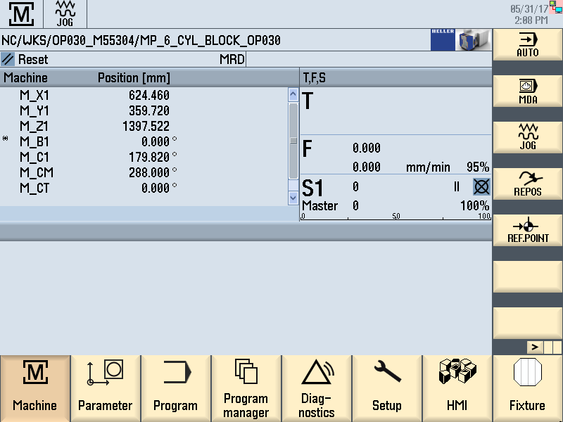
Functions in Jog ModeThe machine has the following NC axes for workpiece machining (main axes): 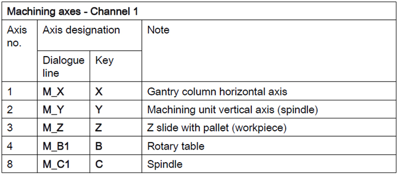
Manual mode is not intended for use during production. Its purpose is to enable the machine axes to be moved to a desired position for setting up or maintenance. Displaying NC-axesStep 1:
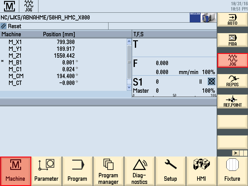
Preconditions for the main operator panel:
Press the Setup key. Step 2:
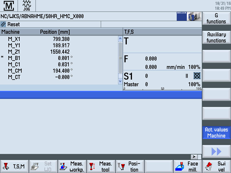
Change to "JOG" NC mode with JOG. Selecting the NC axisStep 1:Use Axis key X/Y/Z to select the axis to be moved.
The lamp of the selected axis lights up. Step 2:Press the Next Axes key. Traversing axisStep 1:
Select the correct Direction keys -/+ according to direction. Step 2:Hand on feed override, To check the axis movement in manual mode, proceed as follows::
Use the Feed override to increase the traverse speed to the desired value. Release Direction key when the desired position is reached. Further options on axis positioning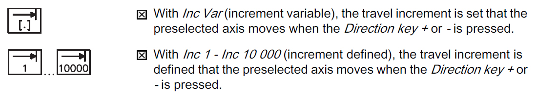
In "MDA" (Manual Data Automatic) NC mode, part programs are
produced and processed block-by-block. To do so, the co-ordinates
of the travel positions and the additional functions (preparatory
conditions, auxiliary functions ...) are entered in the "MDA program"
window. The control processes the entered blocks after the NC start
key is pressed. Manual spindle rotationStep 1: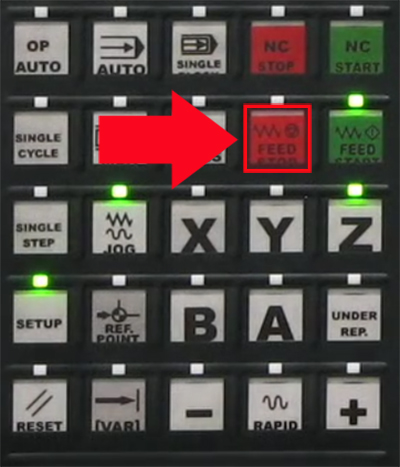
The spindle can be rotated manually at a correspondingly lower
speed of rotation. The sequence must be strictly observed for the
following operating steps.
Press the Feed/Spindle Stop key if the spindle has not yet stopped. The associated LED comes on as soon as "Spindle stop" has been accepted by the control. Step 2: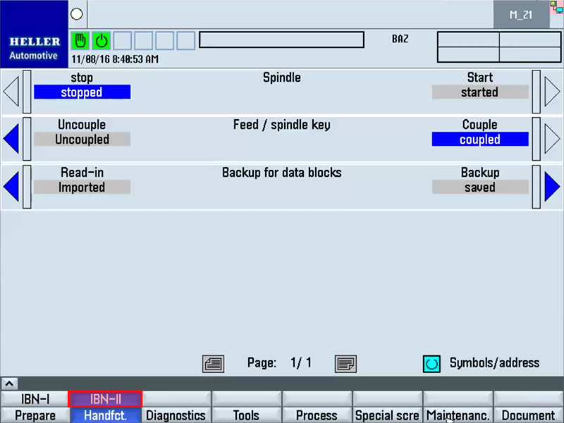
The effect of the Feed/spindle start key must be coupled to the
spindle via the "Feed/spindle key" HMI function (see "Service
functions - IBN II). Step 3:Open work area safety door. Step 4: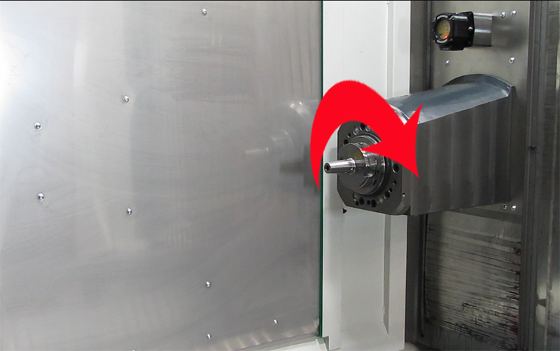
Slowly rotate the spindle so that the Safety Integrated monitoring device cannot trip. On completing the manual spindle rotationStep 1:Close work area safety door. Step 2:Press the Lock/unlock safety door key. Step 3:Press the Feed/Spindle Start key. Manual Tool Change in Jog ModePreconditions:
Step 1:The "Axis- to the change position" function traverses the X and Y-axes into the tool change position. Step 2:Place new tool at provisioning place. Step 3:Open tool change safety door. Step 4:Align spindle. Step 5:Move axis position to change position. Step 6:Rotate tool gripper 90° towards spindle. Step 7:Unclamp old tool in spindle Step 8:Tool gripper stroke and 180° rotation {replace old tool with new tool} Step 9:Clamp new tool in spindle. Step 10:Rotate tool gripper 90° in home position. Step 11:Move old tool into magazine. Step 12:Close tool changer safety door. HMI screen "WZW", page 1Step 1:Press upper horizontal softkey "Tool changer". 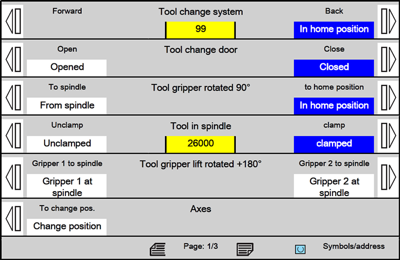
Precondition:
Tool change door Tool gripper rotated 90°>
Tool in spindle Tool gripper lift rotated +180° Axes Function diagram-
HMI screen "WZW", page 2Step 1:Preconditions:
Press the Page up key. 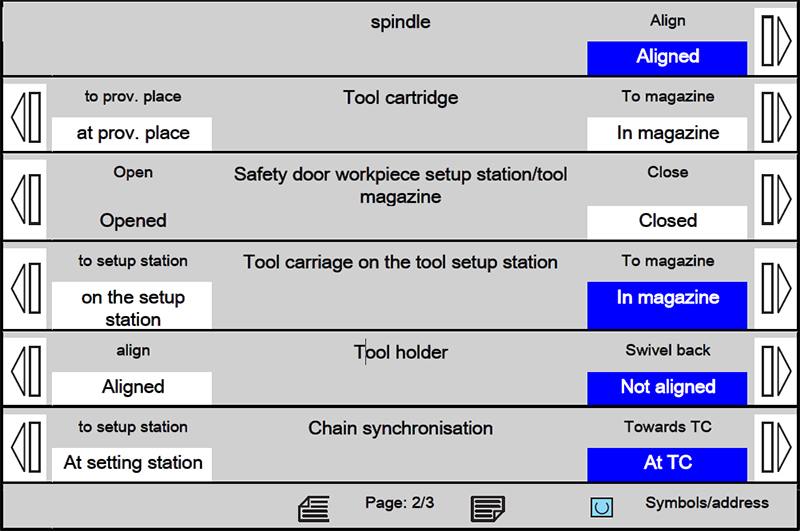
Spindle Tool cartridge Safety door workpiece setup station/tool magazine Preconditions for collision monitoring on:
Preconditions for collision monitoring off:
As long as the tool loading station safety door is open, no tool change functions can be carried out. Tool carriage on the tool setup station
Preconditions for collision monitoring off:
Tool holder
Functions Diagram-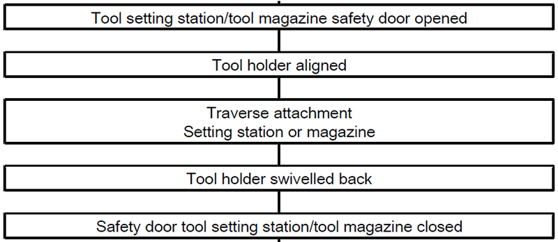
HMI screen "WZW", page 3Step 1:Preconditions:
Press the Page up key. 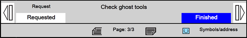
Check ghost tools Pre-settingsStep 1:
Preconditions:
Press the Setup key. Step 2:Press the Setup button. Connecting the HT8Step 1:Press and hold the Bypass E-Stop key at the stationary operating
unit. Step 2:Open Work Area Safety Door Activating JOG mode (on HT8)Step 1: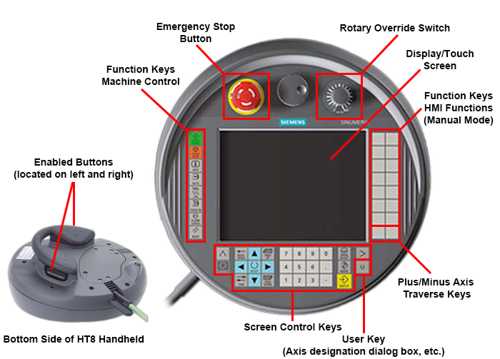
Preconditions:
Press the JOG key. Selecting NC-axis, activating the direction keysStep 1: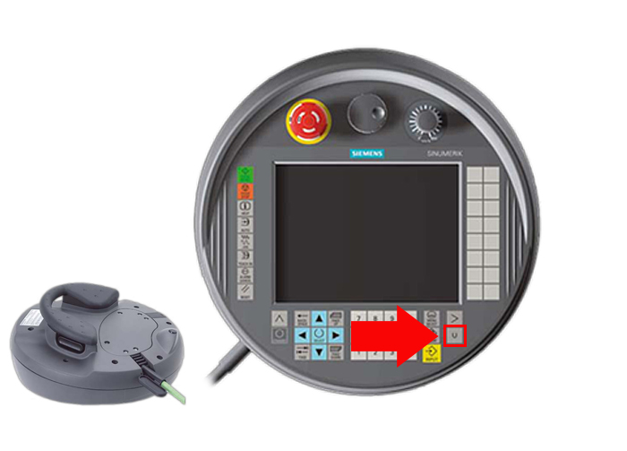
Press the U (User) key. Step 2: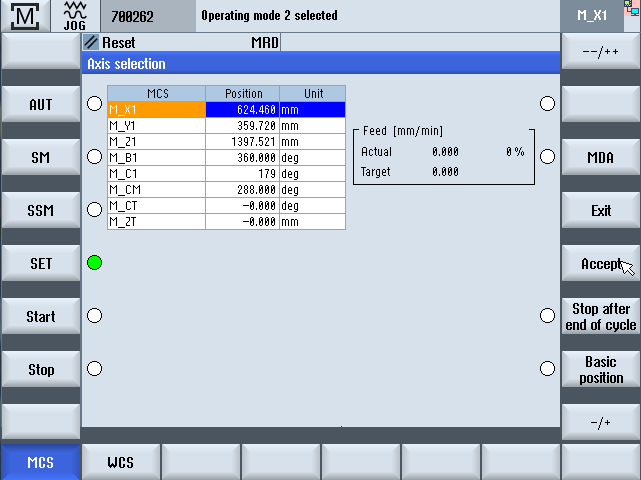
In addition to the axis selection, Feed direction keys + / - and Rapid traverse direction keys ++ / -- are activated as softkeys. These functions can be executed via the keys assigned on the right. Traversing NC-axisStep 1: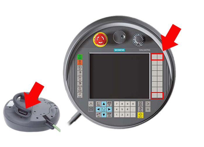
2-hand operation:
at the main operating unit:
Step 2: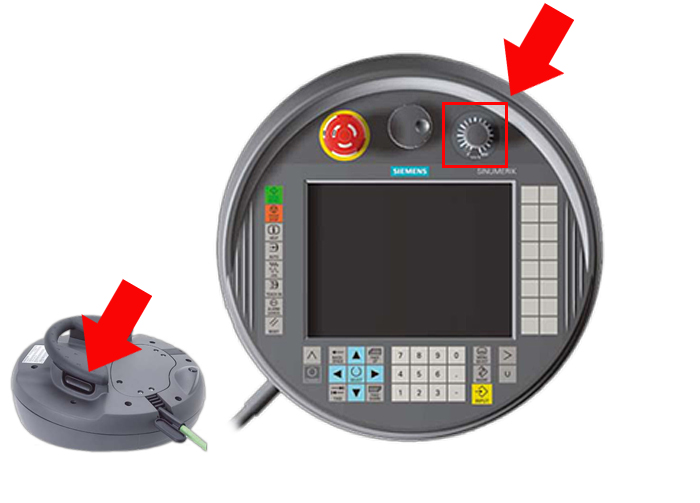
Turn back Feed override to 0%. Then set feed override to a low value
(e.g. 10%). Step 3:

Either Or Step 4:
Use the Feed override to increase the traverse speed to the desired
value. Start of repetition for further traverse motion. Remove HT8Step 1:Press the "Enable" on the HMI When the HT8 is connected - the disable will be active on the HMI screen. Before the HT8 can be removed, the "enable" will have to be selected on the HMI - This will allow the switchover to occur from the HT8 to the HMI when the HT8 is removed. Step 2:Press and hold the Bypass E-Stop key at the stationary operating
unit. Step 3:Exit Setup Mode- Go back into Auto Mode. Step 4:Close Work Area Safety Door Individual functions of the Pallet ChangerPreconditions:
ExplanationPallet Changer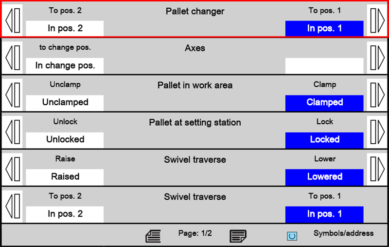
The "Pallet changer" function enables the pallet changer to be traversed to the home position following an abort situation. The residual movements are executed to traverse the pallet changer to the next home position. If the pallet changer is already in the home position, no movement is executed. Preconditions:
Axes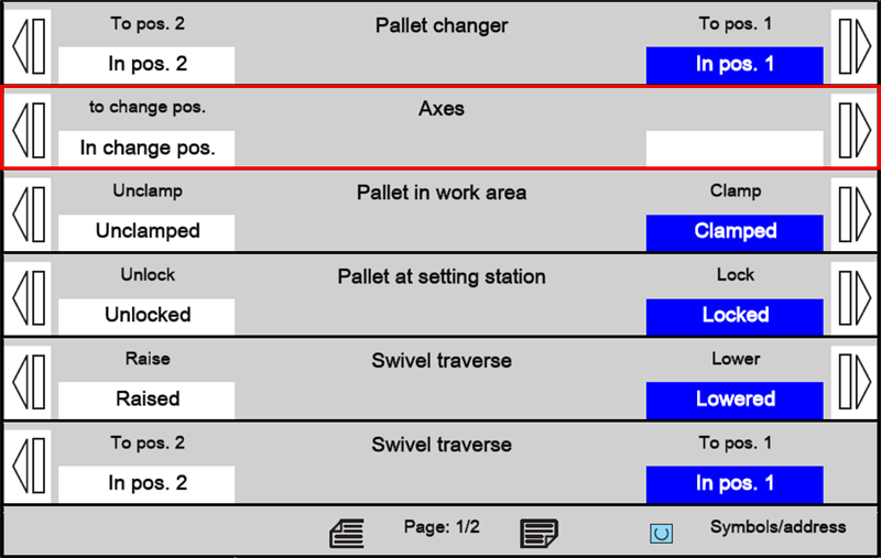
The "Axes" to "Change position" function moves the NC axes of the machine to their pallet change position. Preconditions:
Pallet in Work Area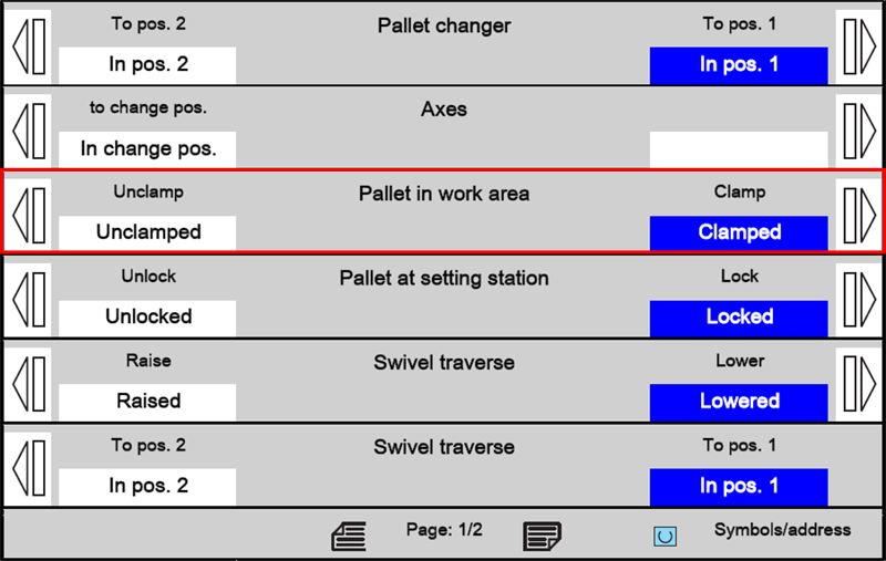
The "Pallet in work area" function clamps or unclamps the pallet on the rotary table in the machining area. With the "Hydraulic workpiece clamping" option, the coupling elements of the pallet are, in addition, coupled to or released from the rotary table. The hydraulic pressure for the clamping fixture is maintained during a pallet changing operation. Preconditions:
Pallet at Setting Station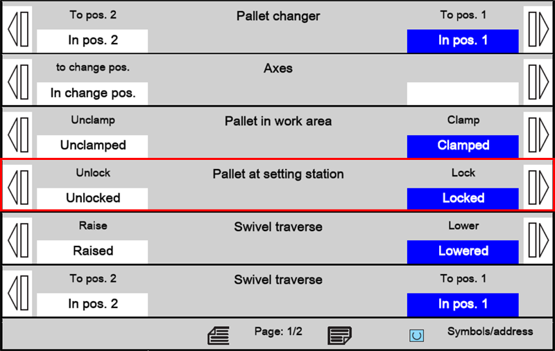
The "Pallet at setting station" function locks or unlocks the pallet on the loading station. With the "Hydraulic workpiece clamping" option, the coupling elements of the pallet are, in addition, locked to unlocked at the setting station. The hydraulic pressure for the clamping fixture is maintained during a pallet changing operation. Preconditions:
Swivel Traverse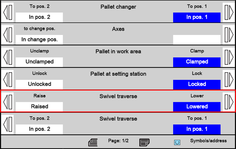
The "Swivel traverse" function raises or lowers the rotary plate by 65 mm at the rotary table or the workpiece setting station. Preconditions:
Swivel traverse - In pos. 2/In pos. 1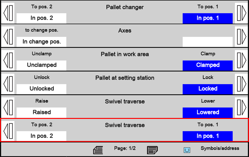
The "Swivel traverse position 1 or 2" function swaps the pallets at the loading station and the work area with a 180° motion. Preconditions:
Pallet Change in JOG ModeStep 1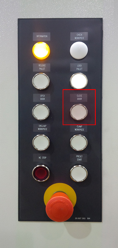
Close and lock front setting station door (this occurs at front push button panel) Step 2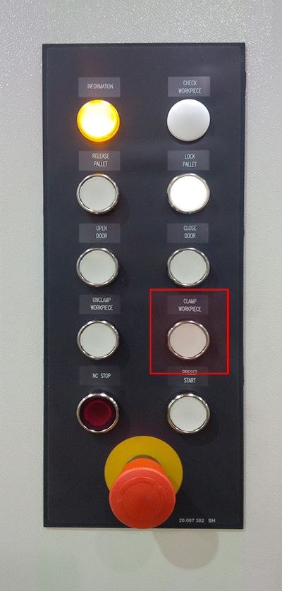
Clamp Fixture (this occurs at front push button panel) Step 3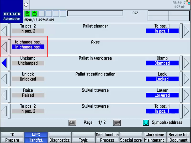
Traverse NC axes to change position - this will move the Z and B axes to the pallet change position (this occurs at HMI Panel) Step 4Unclamp pallet in work area (this occurs at HMI Panel) Step 5Unlock pallet at setting load station (this occurs at HMI Panel) Step 6Lift Swivel traverse (this occurs at HMI Panel) Step 7Position 1 or 2 (this occurs at HMI Panel) Step 8Lower swivel traverse (this occurs at HMI Panel) Step 9Clamp pallet in work area (this occurs at HMI Panel) Step 10Lock pallet at setting load station (this occurs at HMI Panel) Displaying NC-axesStep 1:
Preconditions for the main operator panel:
Press the Setup key. Step 2:
Change to "JOG" NC mode with JOG. Selecting the NC axisStep 1:Use Axis key X/Y/Z to select the axis to be moved.
The lamp of the selected axis lights up. Step 2:Press the Next Axes key. Moving The AxisStep 1:Open Work Area Safety Door Step 2:Select Setup Mode Step 3:Hold in (press) the approval key. Step 4:Select Automatic Mode Step 5:Close Work Area Safety Door |