Z-Axis Ballscrew Replacement
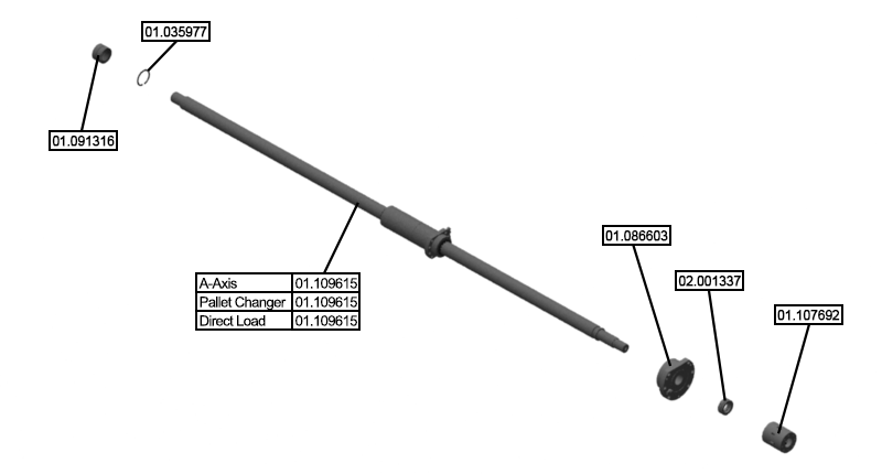
Parts List
Reference Files
Tools Required
Torque Chart
Step 1: ECPL
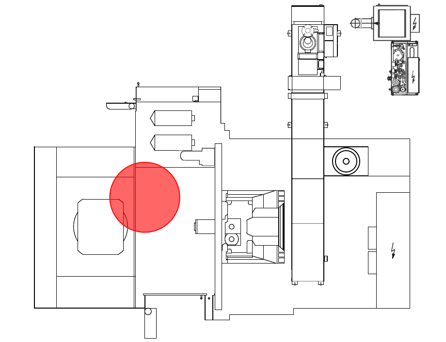
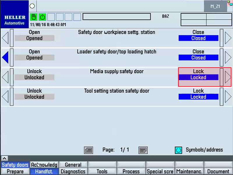
Step 2: Open Work Area Safety Door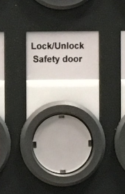
Step 3: Open Concertina CoverStep 4:Refer to Z-Axis Motor Replacement
Refer to steps 1-4 of the Z-Axis Motor Replacement procedure for instructions on removing the motor. Click the back button in your browser to return to this procedure. Step 5: Remove Frontal Lubrication LineStep 6: Open Rear Maintenance Door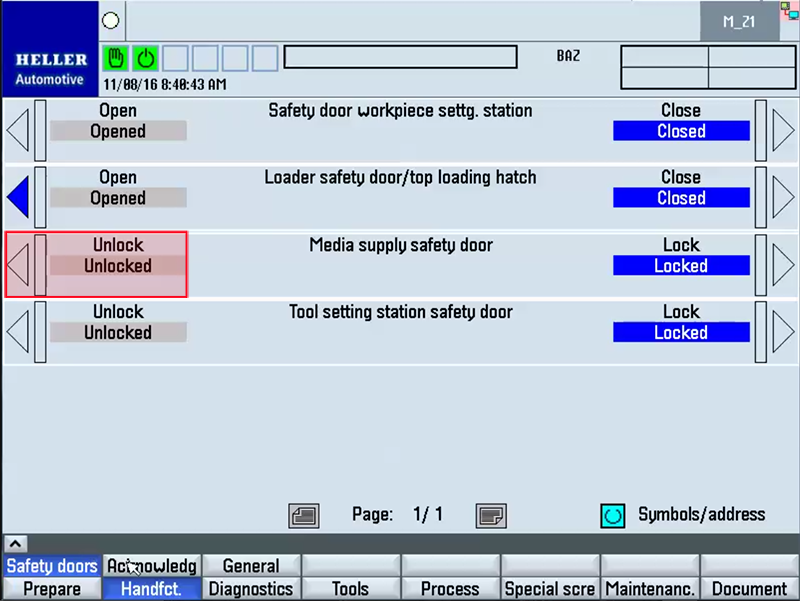
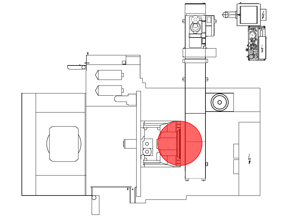
Step 7: Remove Rear Lubrication LineStep 8: Remove Socket Head ScrewsStep 9: Remove Ball Nut ScrewsStep 10: Insert Jack Screws into Head CapStep 11: Remove Ball Screw AssemblyStep 12: Remove / Install New Needle Bearing
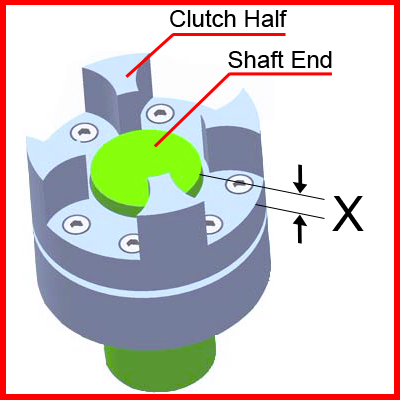
Step 13: Measure Coupling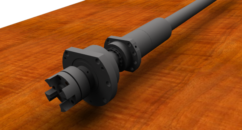
Step 14:Lubricate BearingStep 15: Install BearingStep 16: Install Locknut / Coupling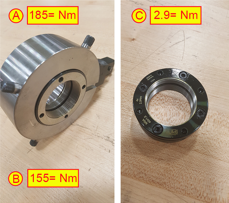
Step 17: Install Inner RaceStep 18: Install InsertStep 19: Clean Bearing Mounting Surface
Step 20: Clean Ballnut Mounting Surface
Step 21: Insert Ballscrew Assembly into MachineStep 22: Insert Socket Screw and Torque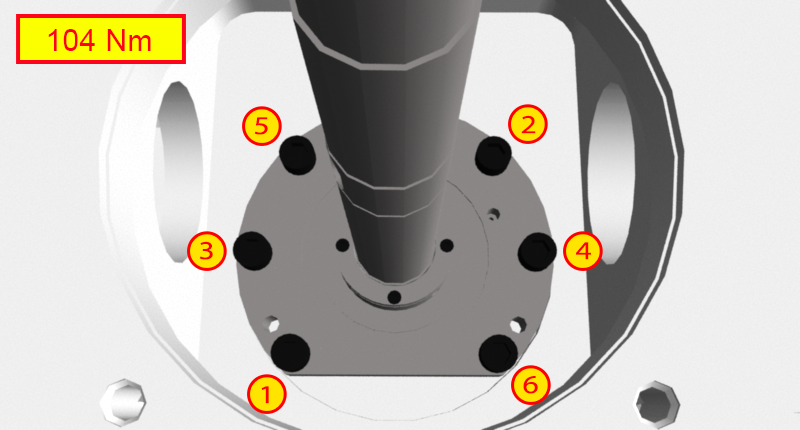
Step 23: Insert Ball Nut Screws and Torque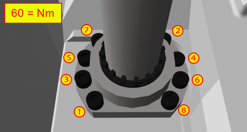
Step 24: Install Frontal Lubrication LineStep 25: Install Rear Lubrication LineStep 26: Close Rear Maintenance Door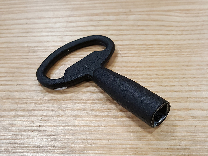
Step 27:Refer to Z-Axis Motor Replacement
Refer to steps 1-4 of the Z-Axis Motor Replacement procedure for instructions on removing the motor. Click the back button in your browser to return to this procedure. Step 28: Close and Secure Concertina CoverStep 29: Close Work Area Safety Door
Step 30: ECPL
Step 31: Activate Lubrication and Run-in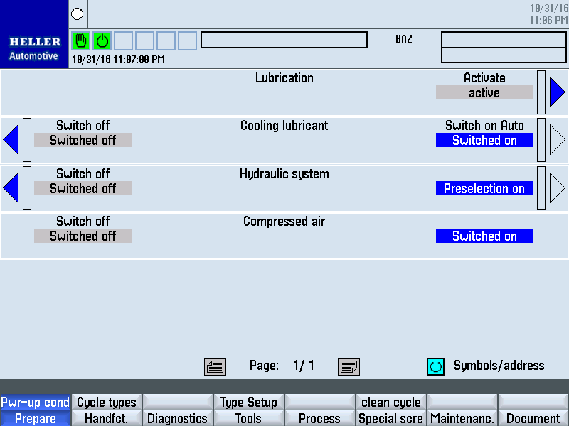
Activate the Lubrication Cycle several times via the HMI - Prepare - Pwr-up Cond. HMI screen. After the lubrication cycles have been completed, it is now necessary to run-in the ballscrew. This can be accomplished by moving the axis back and forth along the entire length of travel at half rapid speed for 30 minutes. Then allow the ballscrew to cool for 45 minutes. Once completed, the ballscrew can now be fully loaded. |
|||||||||||||||||||||||||||||||||||||||||||||||||||||||