Reference point of CM Axis (magazine)
Reference Files
Tools Required
Torque Chart

The Magazine axis motor is utilized for positioning of the magazine to the tool changer provisional place. When magazine place 1 is aligned to the tool changer provisional place, the axis position will be 360.000 or 0.000. The secondary external encoder is utilized for positioning of the magazine to the tool loading station. Both of these positions are determined by using a steel straight edge and determining the deviation between the two guides. Once these deviations has been determined, the calculations can then entered in the CM axis Machine Data. 
Step 1: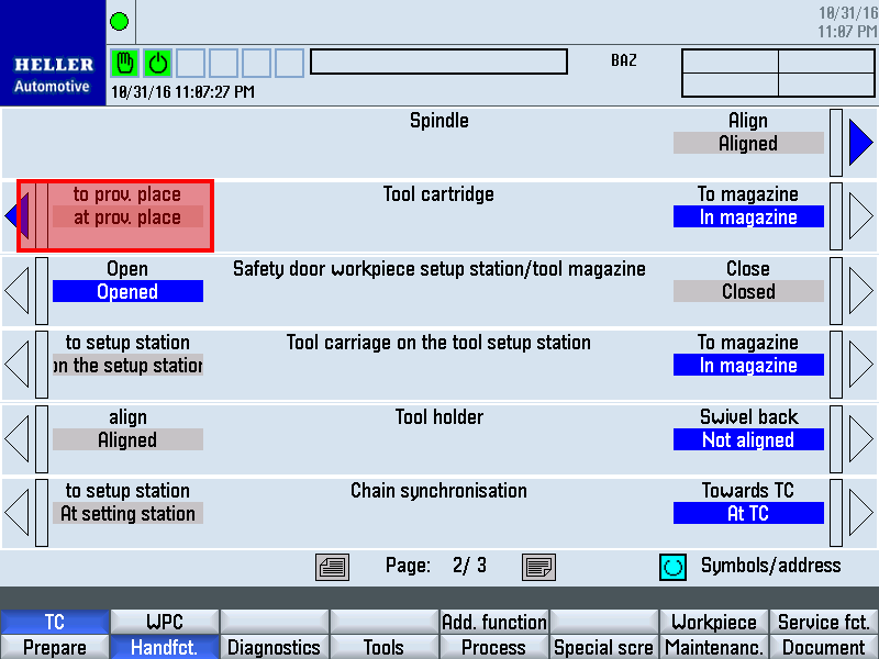
Move magazine place 1 (empty location without tool cartridge) to the conveying station towards tool changer. Step 2:Position the linear axes such that the tool changer door is easily
accessible: Step 3: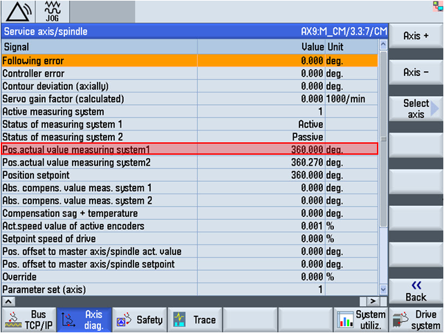
Check measuring system position display: Step 4: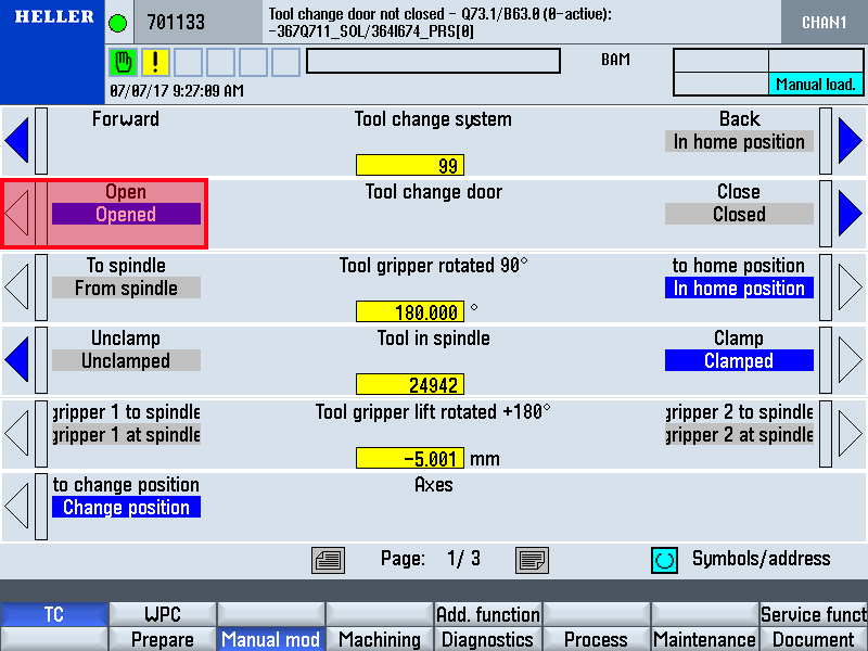
Select the "Tool change individual functions" main menu. Step 5: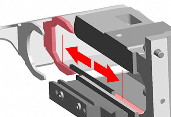
Determine deviation between target and actual position.
Step 6: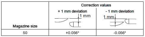
Converting the deviation to angular degrees. Observe positive and negative values according to the following tables: Step 7: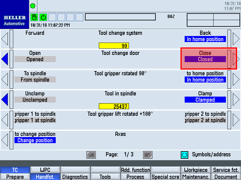
Remove support from the tool change door. Step 8: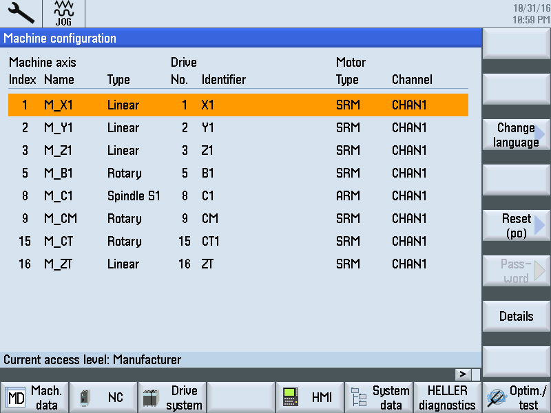
Insert EKS key, select setup, mach. dataMD, Axis MD. Step 9: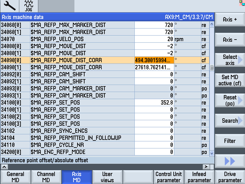
Enter adjustment value:
Step 10: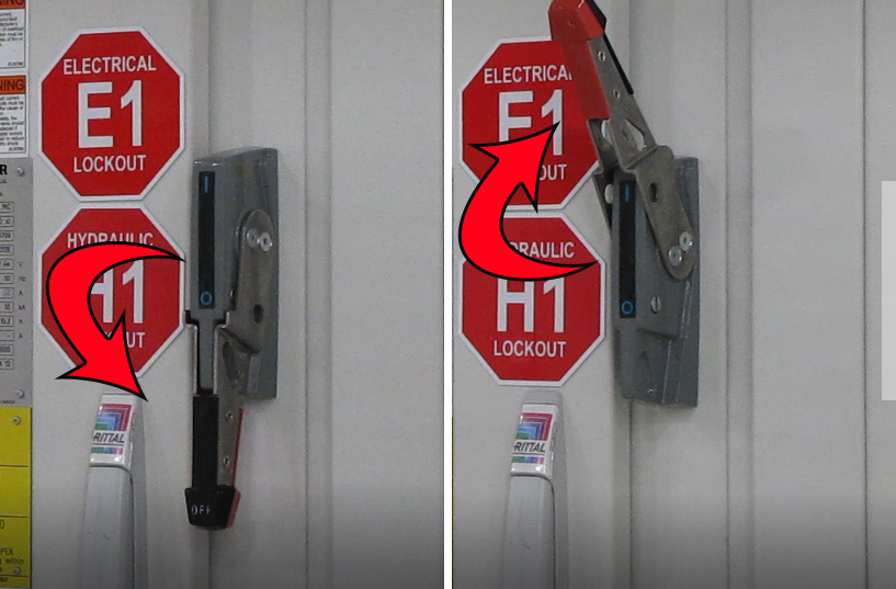
Turn the main switch off and on again. The actual position of the tool magazine is displayed in the actual value display of the main operator panel. Step 11:Checking adjustment and readjust if necessary Step 12: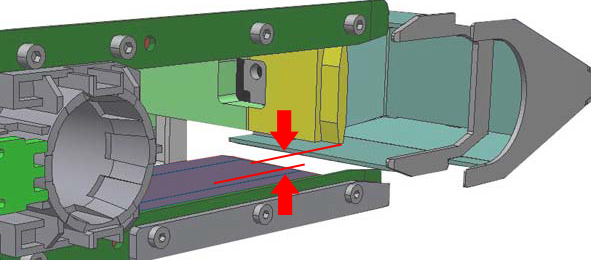
Because measuring system 2 sits flush over the tool setting station, tensioning has only a slight effect on this side. After repeated tensioning however, the deviation may exceed tolerance permitted here. The cartridge transport between conveying station and tool changer provisioning place is smooth. Step 13:Move magazine place 33 on the conveying station towards the tool changer. Magazine place 1 (empty location without tool cartridge) is located on the conveying station towards the tool setting station. Step 14: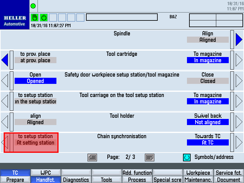
Open intermediate door: Step 15: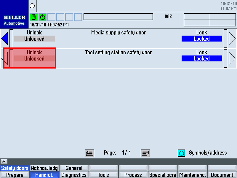
The control switches over to measuring system 2. The chain-type magazine moves up by the offset between the two measuring systems. Step 16: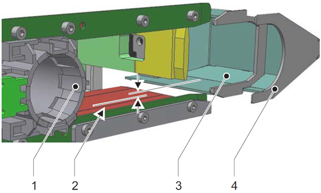
Determine the difference between conveying station and tool setting station Step 17:
Determine deviation between target and actual position.
Step 18: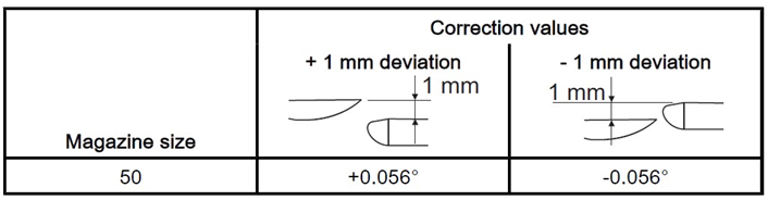
Converting the deviation to angular degrees. Step 19: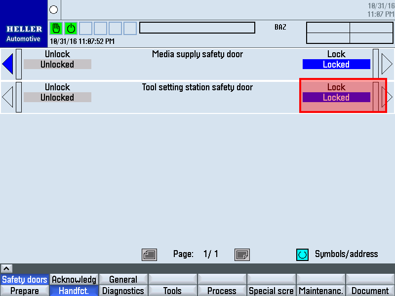
Remove support from intermediate door. Step 20: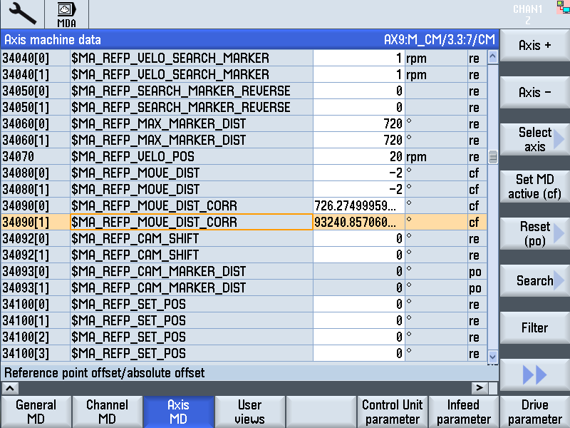
Step 21:Enter adjustment value:
Step 22:
Turn the main switch off and on again. The actual position of the tool magazine is displayed in the actual value display of the main operator panel. Step 23: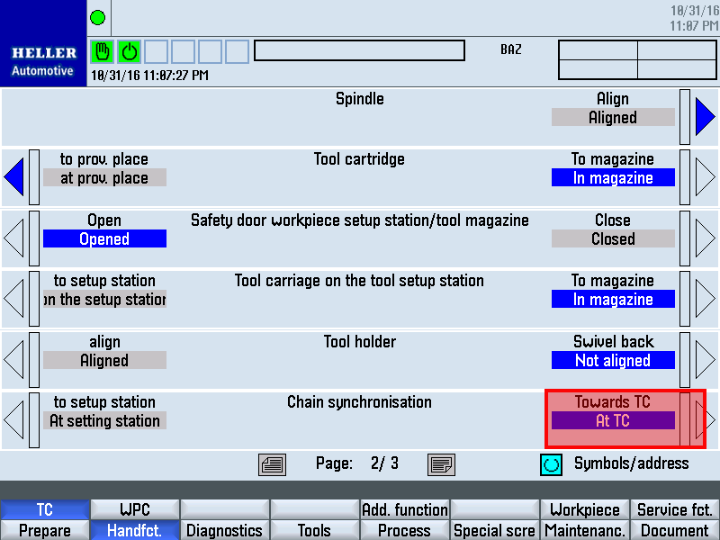
Synchronize chain-type magazine with the tool setting station via individual function "chain synchronization". Step 24:Run the tool magazine through its complete cycle again in both directions. Check height of the conveying station. Readjust deviations. Proceed as previously with the first adjustment. Step 25:You have checked the adjustment and not found any deviations. Step 26:
Move one magazine place with tool cartridge on the conveying
station towards tool setting station. Step 27: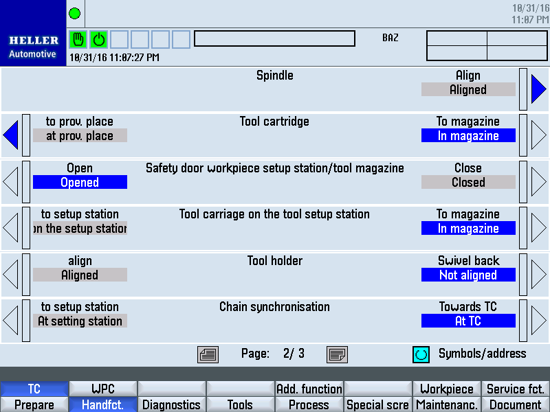
Use the "Tool cartridge on tool setting station" individual function to move the tool cartridge to and fro between conveying station and tool loading position. At the same time, observe the tool cartridge movement. The tool cartridge must move back and forth without jerking.
Individual function "Tool holder" to "swivel back". |
|||||||||||||||||||||||||||||||||||||||||||||||||||||||||||||||||||