Function of Pallet Changer
Reference Files
Tools Required
Torque Chart

Step 1: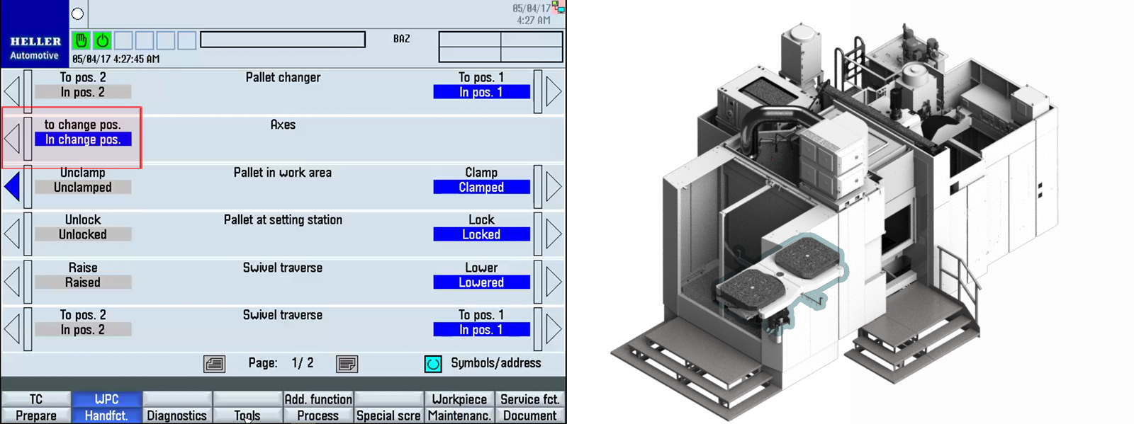
The machine axes and setting station are in the pallet change position. Step 2: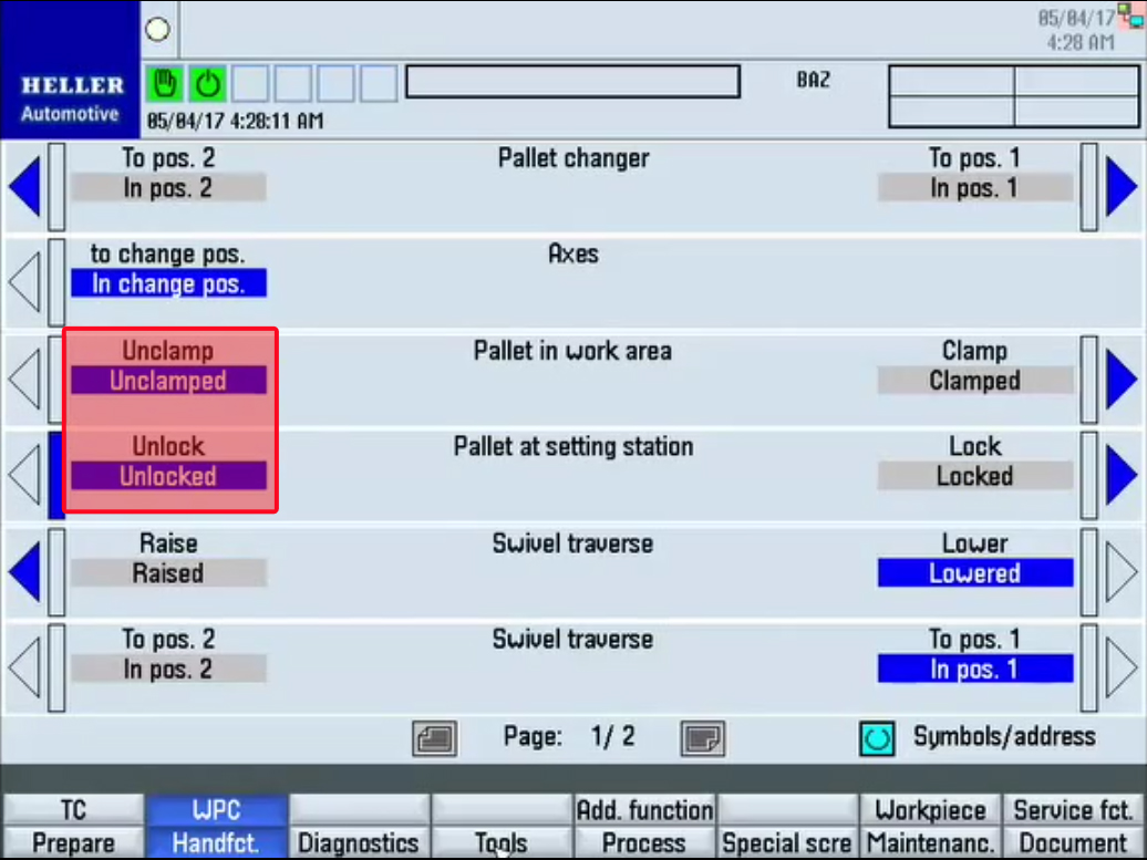
The setting station pallet and work area pallet are unclamped. Step 3: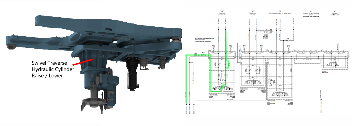
Fluid is supplied to the raise side of swivel traverse raise lower hydraulic cylinder which in turn raises the pallets. Step 4: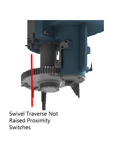
When fully raised, the swivel traverse raised proximity switch is on. Step 5: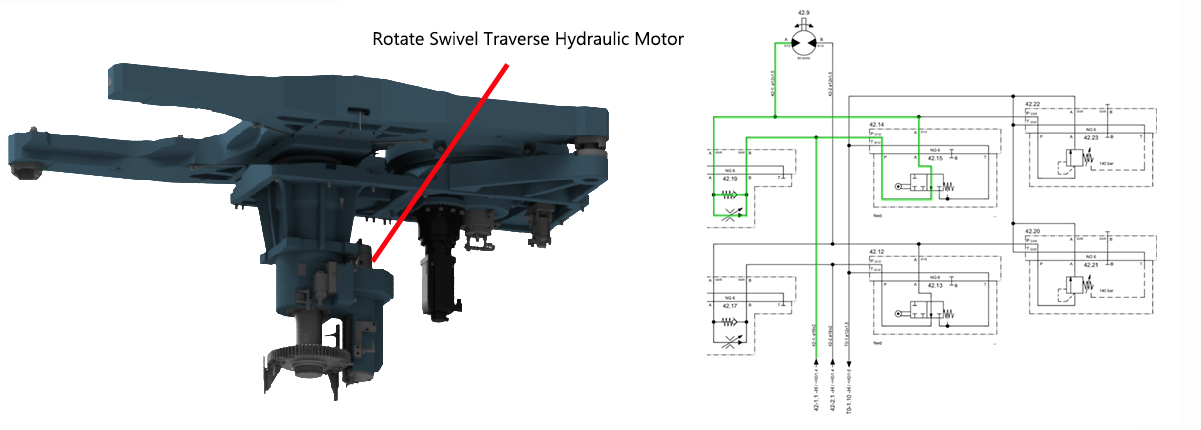
Fluid is supplied to the rotate swivel traverse which in turn rotates the pallet changer. Step 6: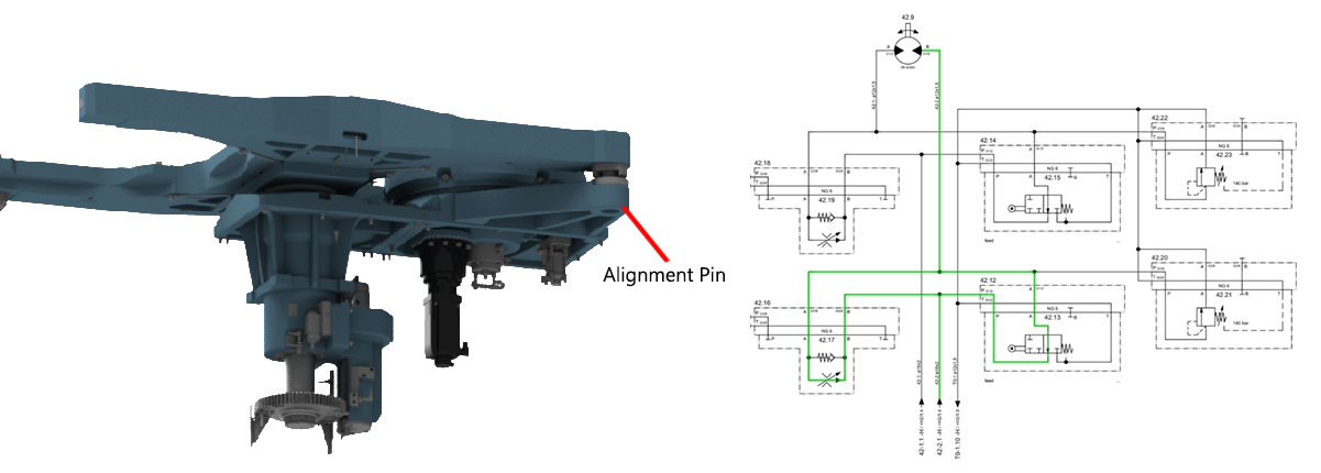
The speed is reduced approximately 100.00 mm away from the alignment pin, when the directional control valve (rollers) are actuated (closed) by the cam lobe ramps. Step 7: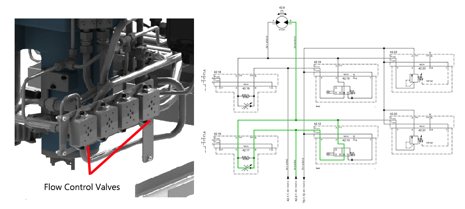
When the directional control valve (rollers) are actuated (closed), all return line fluid is then diverted through the appropriate flow control valve which reduces the pallet changer rotational speed. Step 8: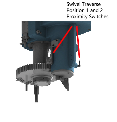
When fully rotated, the swivel traverse position 1 or 2 proximity switch is on. Step 9: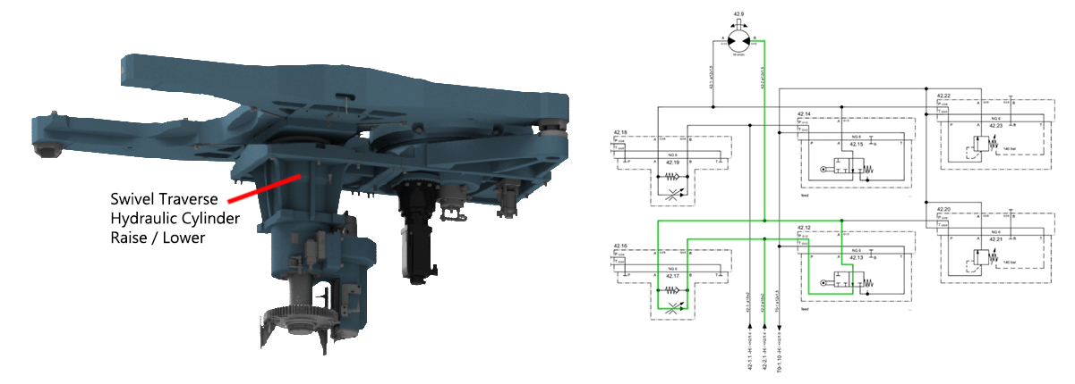
Fluid is supplied to the lower side of the swivel traverse raise lower hydraulic cylinder which in turn lowers the pallets. Step 10:
When fully lowered, the swivel traverse lowered proximity switch is on. Step 11: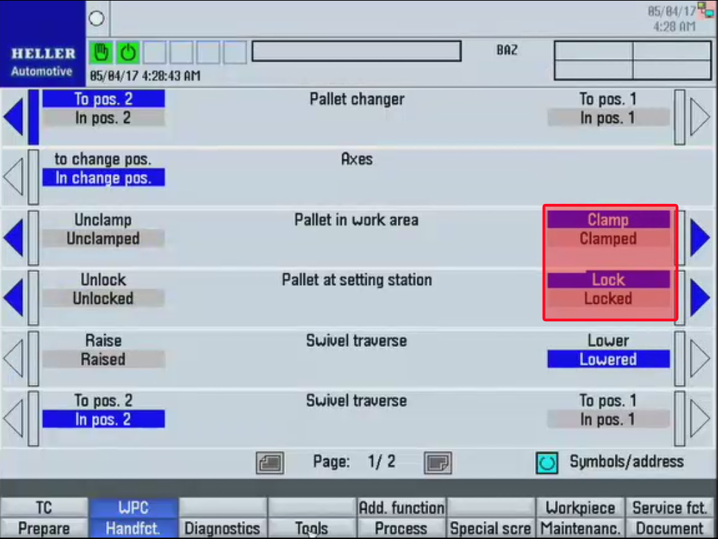
The setting station pallet and work area pallet are clamped. |
|||||||||||||||||||||||||||||||||||||||||||||||||||||||