Reference Point of the Y axis
Reference Files
Tools Required
Torque Chart
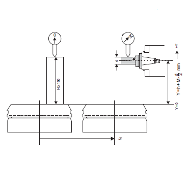
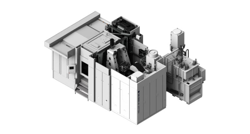
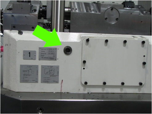
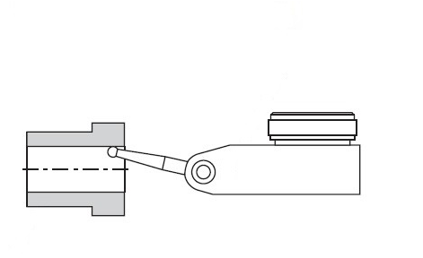
Step 1:You need to determine the actual physical position of the Y axis before you can calibrate the length measuring system. To do this you will need a gauge block and an alignment mandrel, which is inserted into the tool spindle. A comparison measurement with the dial gauge yields the exact Y position Before starting adjustment, determine the exact height of the gauge block and the exact diameter of the alignment mandrel to ensure that any discrepancies from the ideal measurements do not interfere with the calculations. Step 2:The following procedure is taken from a Heller MC20 machine, although the H series machine uses an HSK 100, the same steps apply. Step 3:Y axis reference point using bushing on fixtureTools needed: Step 1:If access to the blank pallet is not possible due to the fixture being installed. The correct axis position can be determined using the fixture bushing. Each machine has a bushing on one face of the fixture that is trammed in using the machine axes after machine installation and runoff has been completed. In addition, there is a plate with the axes positions of the this bushing. Step 2:Jog the axes to the values that are indicated on the bushing plate. With a 2 micron indicator mounted to the spindle, tram the inner diameter of the bushing by adjusting the axes positions and rotating the spindle through 360 degrees. Perform these steps until the indicator reads zero (0.000) total indicator error throughout the entire spindle rotations. Once this has been completed, the axis position found on the bushing plate can be entered in MD 341000 [0] for the respective axis and the calibrating procedure followed. |
|||||||||||||||||||||||||||||||||||||||


