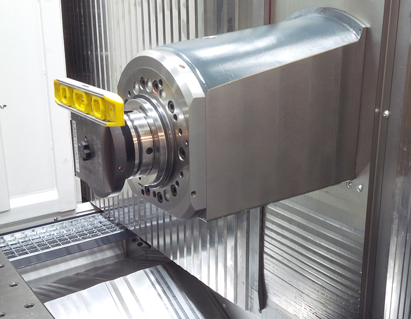
Spindle Replacement
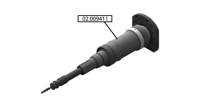
Parts List
Reference Files
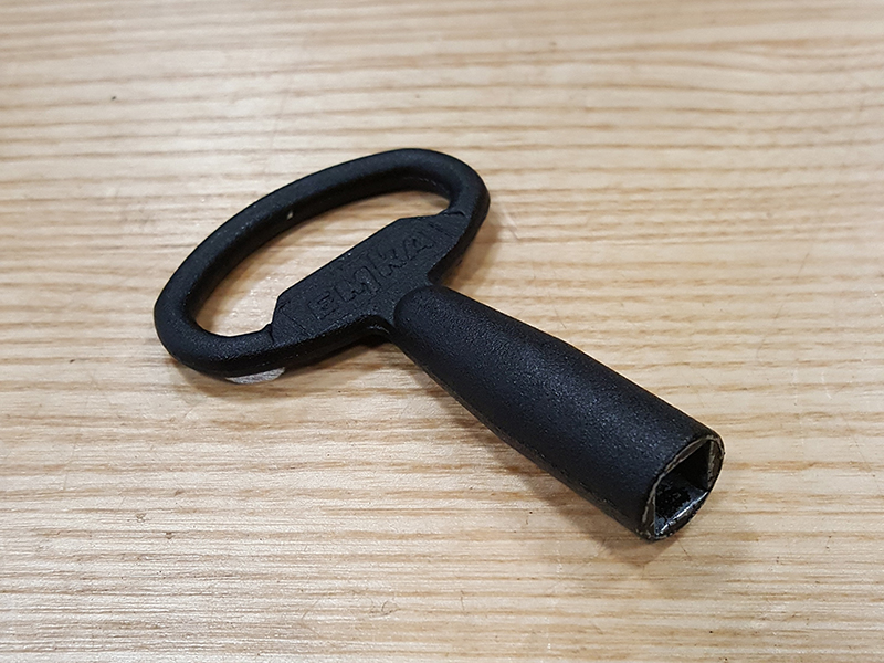
Tools Required
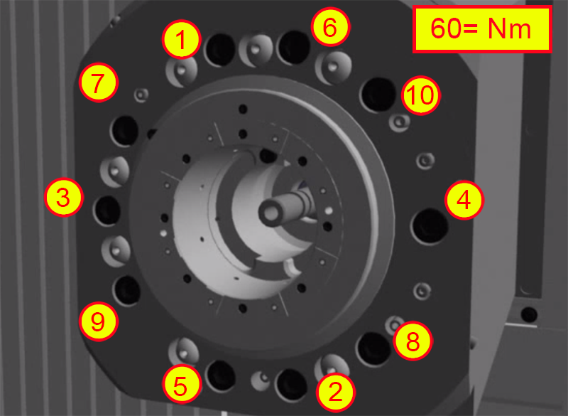
Torque Chart
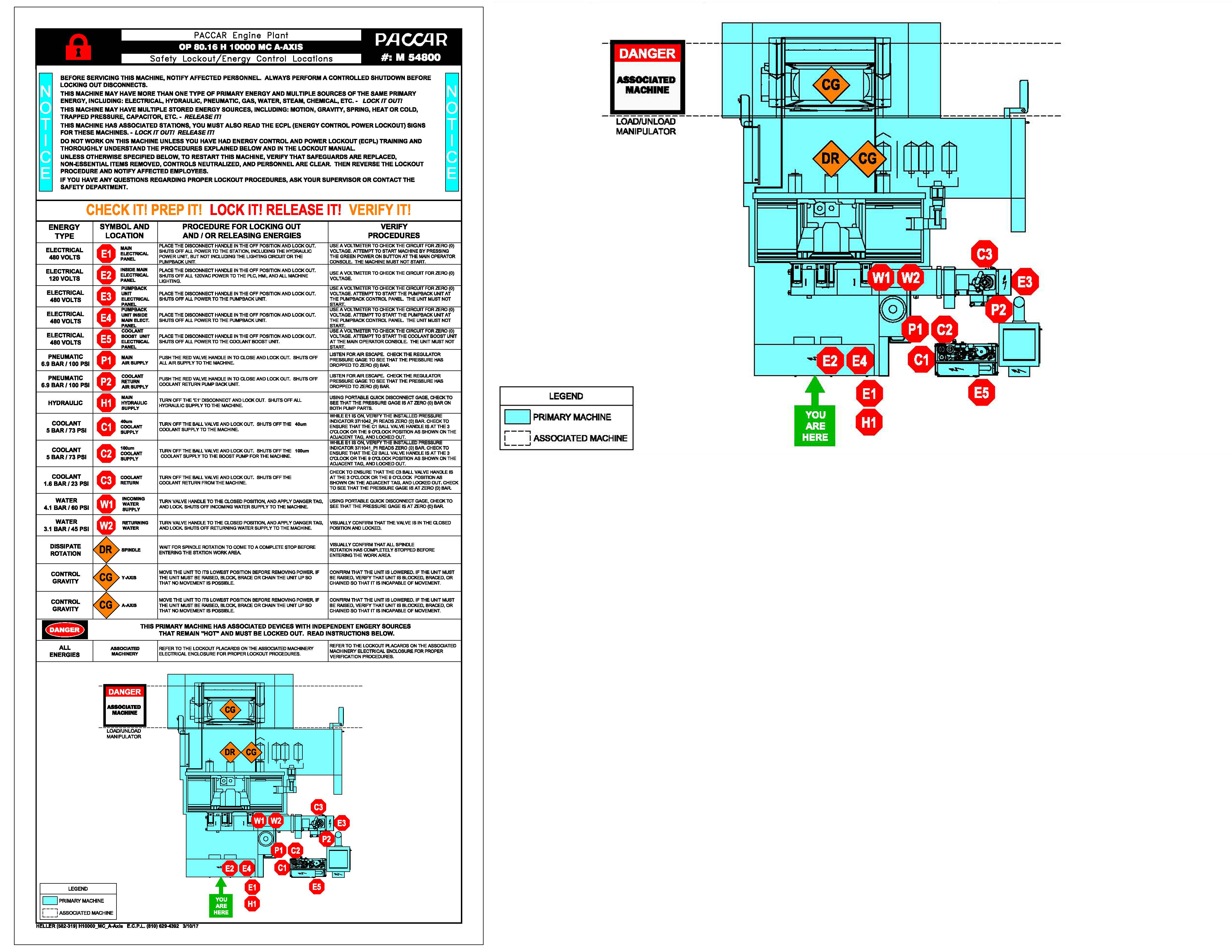
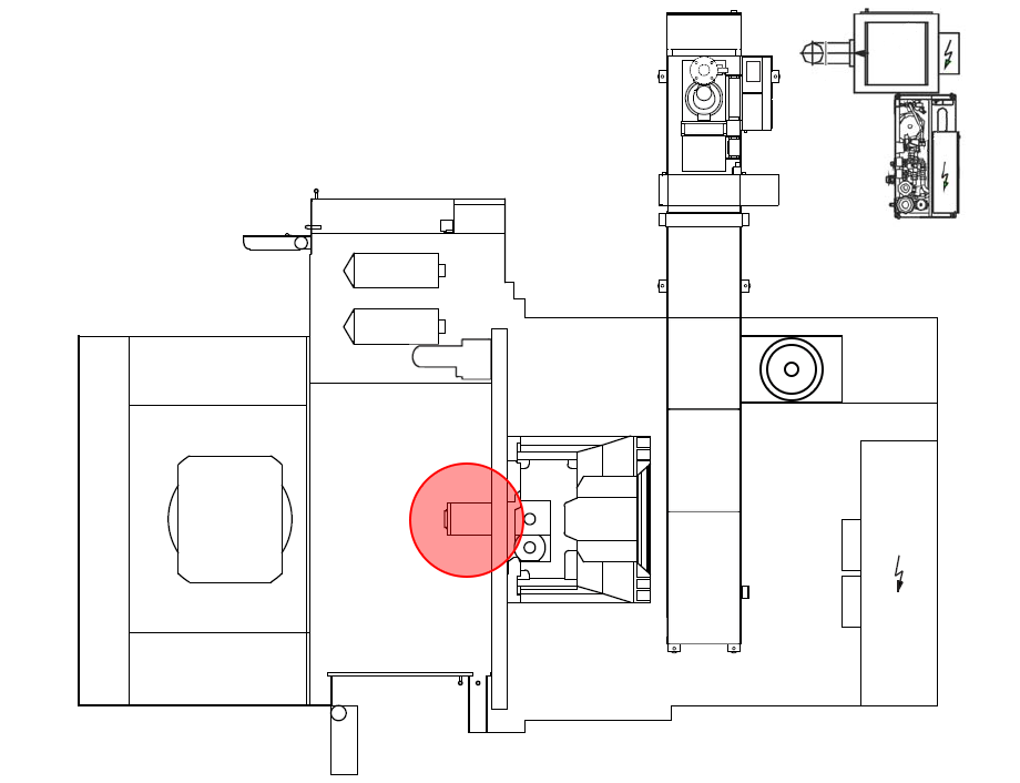
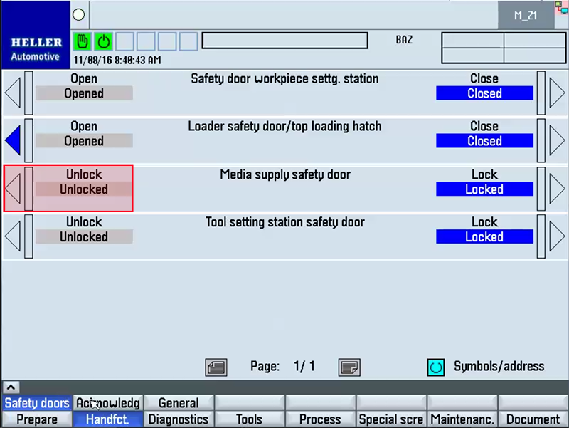
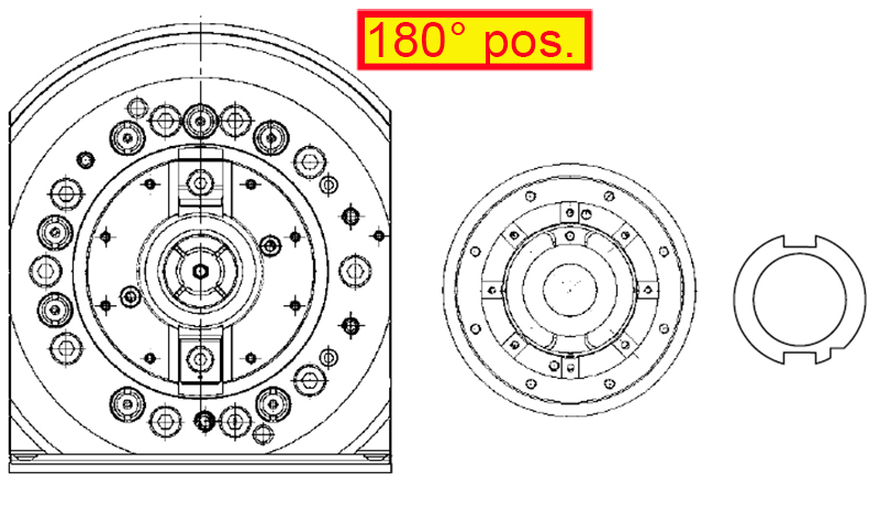
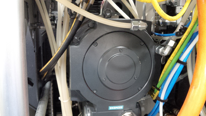
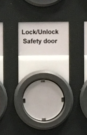
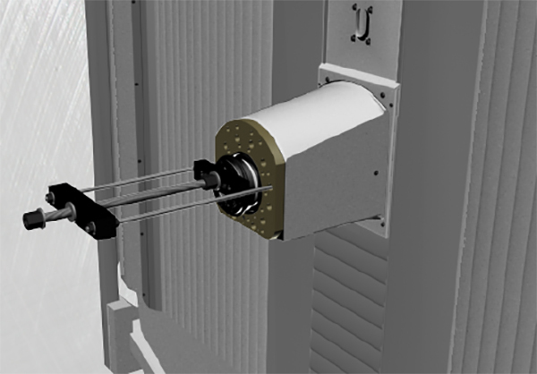
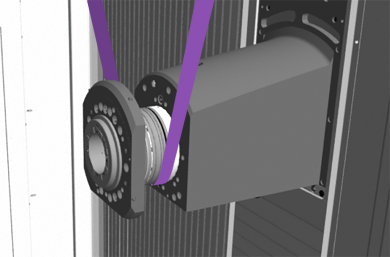
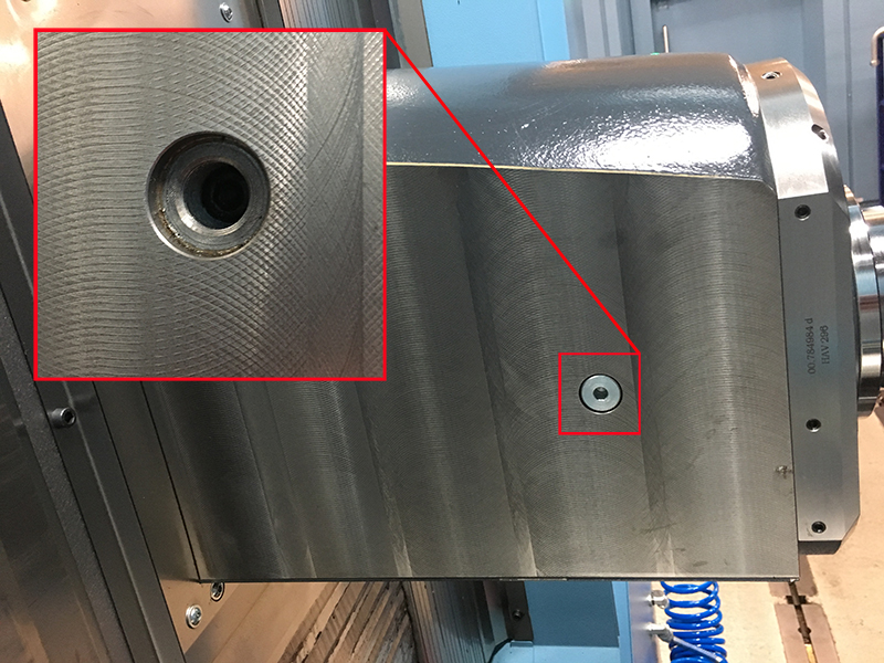
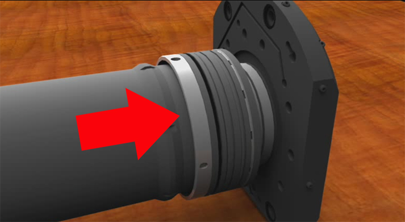
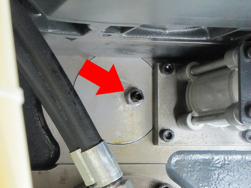
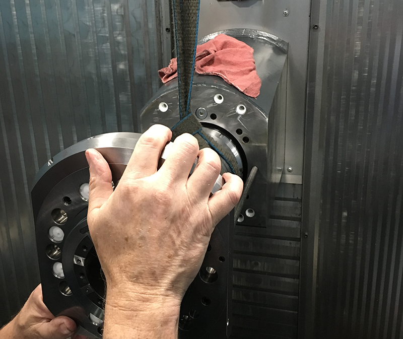
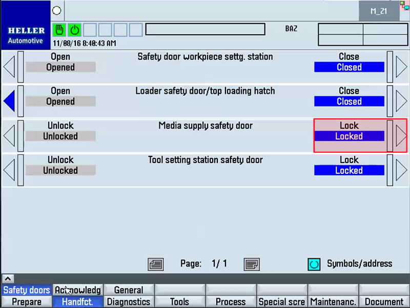
Step 1: ECPLStep 2: Position AxisStep 3: Open Rear Maintenance DoorStep 4: Align Gear Unit to 'locked' position and spindle at 180 degrees (tall drive key at 12 0' clock position)"See procedure: Gear Unit Reference Points" Step 5: Disconnect Services to Spindle RearStep 6: Remove Rotary Coupling"See Procedure:Replacing Rotary Distributor Coupling" Step 7: Open Work Area Safety DoorStep 8: Remove Collet"See Procedure:Collet Replacement" Step 9: Remove Screws and PinsStep 10: Attach Extractor UnitStep 11: Pull Spindle Out to First Shim/Last O-RingStep 12: Support Spindle With Lifting DeviceStep 13: Remove Spindle at 180 degrees (Tall drive key at 12 o' clock position)Step 14: Remove plug and Set ScrewStep 15: Remove and Check Shims For DamageStep 16: Insert Rear Ring Into Housing and Front Ring onto SpindleStep 17: Clean and grease New SpindleStep 18: Replace O-Rings if Needed With a Layer of LubricationStep 19: Check Gear Unit for locked positionStep 20: Use lift Assist and Push Spindle in by Hand to Depth around 70 MM and spindle at 180 degrees.Step 21: Push Into Place at 180 degrees (Tall drive key at 12 o' clock position)Step 22: Install Housing ScrewsStep 23: Cross Tighten ScrewsStep 24: Install plug and Set ScrewStep 25: Return Gear Unit To Unlocked PositionStep 26: Install Rotary Coupling"See Procedure:Replacing Rotary Distributor Coupling" Step 27: Reconnect Services to Spindle RearStep 28: Close Rear Maintenance DoorStep 29: Install Collet"See Procedure:Collet Replacement" Step 30: Close Work Area Safety DoorStep 31 : Check Spindle Zero and Clamping ValuesStep 32: Activate Lubrication and Run-inActivate the Lubrication Cycle several times via the HMI - Prepare - Pwr-up Cond. HMI screen. After the lubrication cycles have been completed, it is now necessary to run-in the spindle machining unit. The temperature has to be monitored during the run-in procedure and compared against the supplied temperature readings in the acceptance report. If the measured values are exceeded, stop immediately and allow the unit to cool before attempting to repeat the run-in cycle. The Spindle Machining Unit should be run-in using the following parameters: Spindle at 25% 4 minutes Downtime 2 minutes Spindle at 50% 4 minutes Downtime 2 minutes Spindle at 75% 4 minutes Downtime 2 minutes Spindle at 100% 4 minutes Once completed, the spindle machining unit can now be fully loaded. Step 33: ECPL |
|||||||||||||||||||||||||||||||||||||||||||||||||||||||||
