Spindle Machining Unit Axis Gearbox Reference Points
Reference Files
Tools Required
Torque Chart
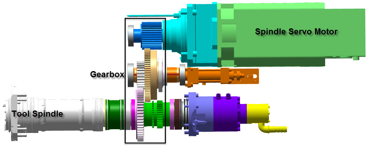
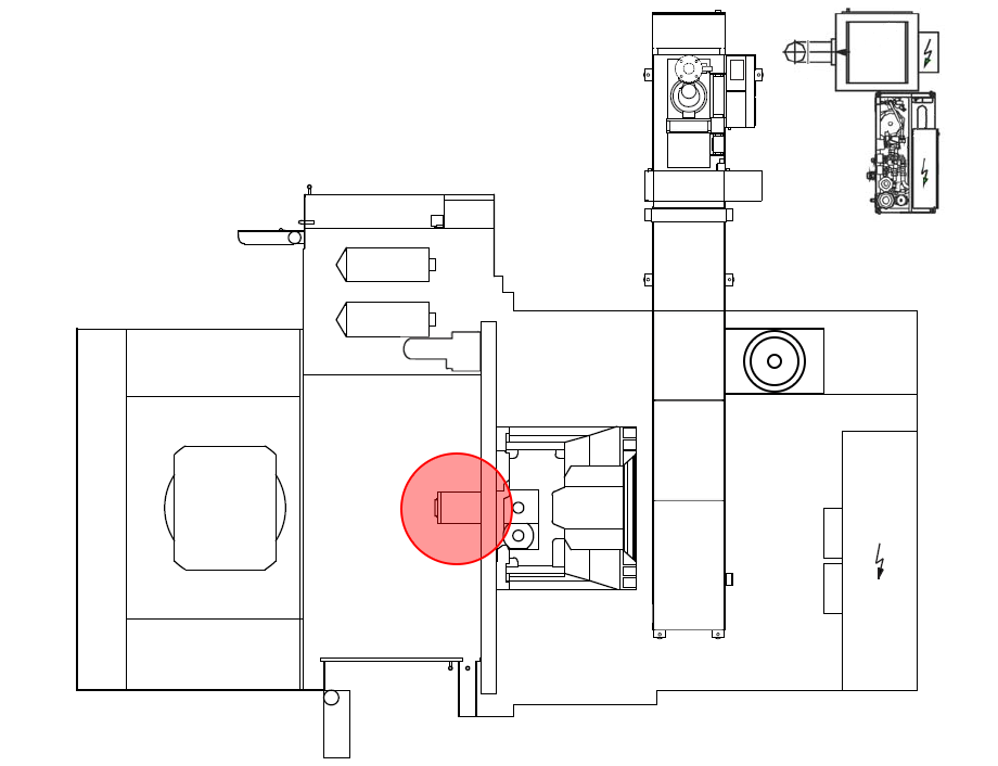
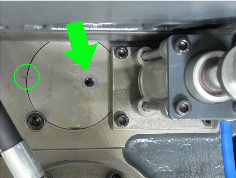
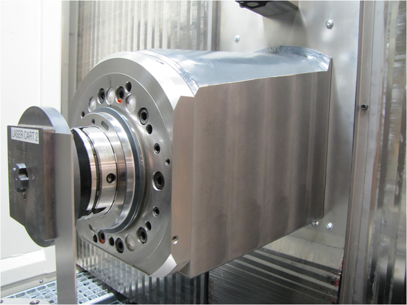
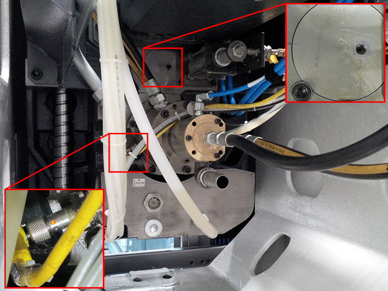
NOTE: THIS PROCEDURE MUST ALWAYS BE CARRIED OUT IF THE MOTOR HAS BEEN REMOVED OR REPLACED, OR IF THE TOOL SPINDLE HAS BEEN REMOVED OR REPLACED WITHOUT FIRST ALIGNING AND LOCKING THE MACHINING UNIT GEARBOX. OVERVIEW: The gearbox of the machining unit as well as the tool spindle is offset from the spindle servo motor encoder zero mark by 180 degrees. It is therefore necessary to determine the machining unit's gearbox shifting points for 4:1 and 1:1 as well as determine the tool spindle 0.000 degree position when in 4:1 and 1:1. Step 1: ECPLStep 2:Unclamp the spindle. Step 3:Open the work area safety door. Step 4:Insert the spindle zero tool. Step 5:Clamp the tool in the spindle. Step 6:Open the rear maintenance door. Step 7:Remove stud and locking nut from checking bore on the back of the unit
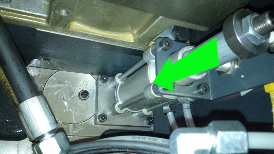
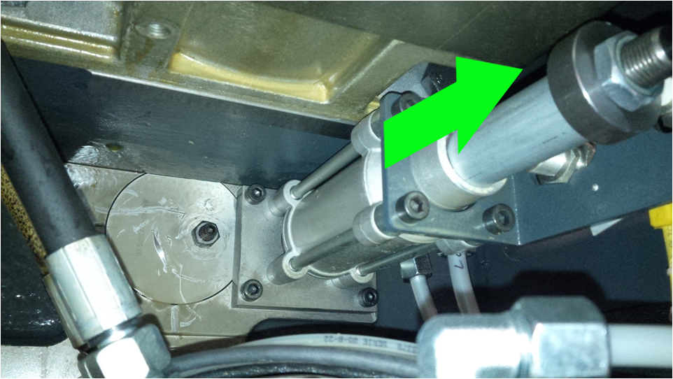
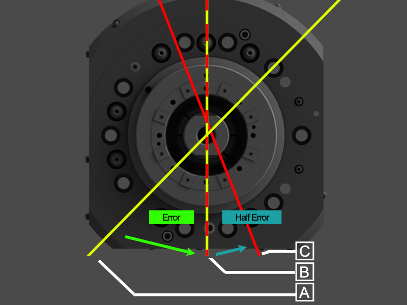
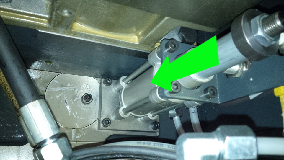
Step 8:Manually switch gears into position 4: 1 By pushing the shift cylinder forward toward the machining area. Step 9:With spindle zero tool installed, manually rotate spindle to 180 degrees The German corner should in the lower right corner of spindle Step 10:On the rear of the spindle gearbox, the dimple should be aligned and the proximity switch should be on (proximity switch is aligned with internal cam) Step 11:If it is not aligned manually rotate the spindle until dimple of the intermediate shaft becomes visible in the checking bore. Step 12:Step 13:Determine the spindle error and rotate by half the error in the opposite direction beyond the zero position. In this example from A to B to C. Step 14:Step 15:Manually rotate the spindle until the dimple of the intermediate shaft becomes visible in the checking bore. Step 16:With spindle zero tool installed, manually rotate spindle to 180 degrees. The german corner shold be in the lower right corner of the spindle. Step 17:Clear position values in control 34100 and 35012, set MD active.
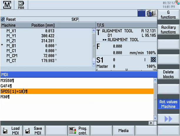
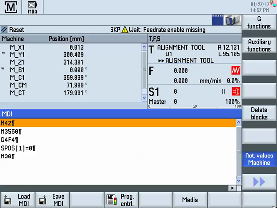
Perform extended NCK reset. Spindle alignment position SPOS=0 is now set in the C1 axis machine data N34100[0] $MA_REFP_SET_POS e.g. 180.033 (for 1:4 cylinder front) N34100[1] $MA_REFP_SET_POS e.g. 180.138 (for 1:1 cylinder back) Gear shift position SPOS = 180 is now set in the C1 axis machine data N35012[1] $MA_GEAR_STEP_CHANGE_POSITION e.g. 180.456 (for 1:4 cylinder front) step 41-42 N35012[2] $MA_GEAR_STEP_CHANGE_POSITION e.g. 180.456 (for 1:1 cylinder front) step 42-41 Step 18:In MDI Mode, enter: Step 19:Spindle will now be out of position. Around 180 degrees.
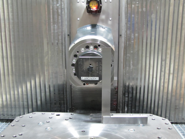
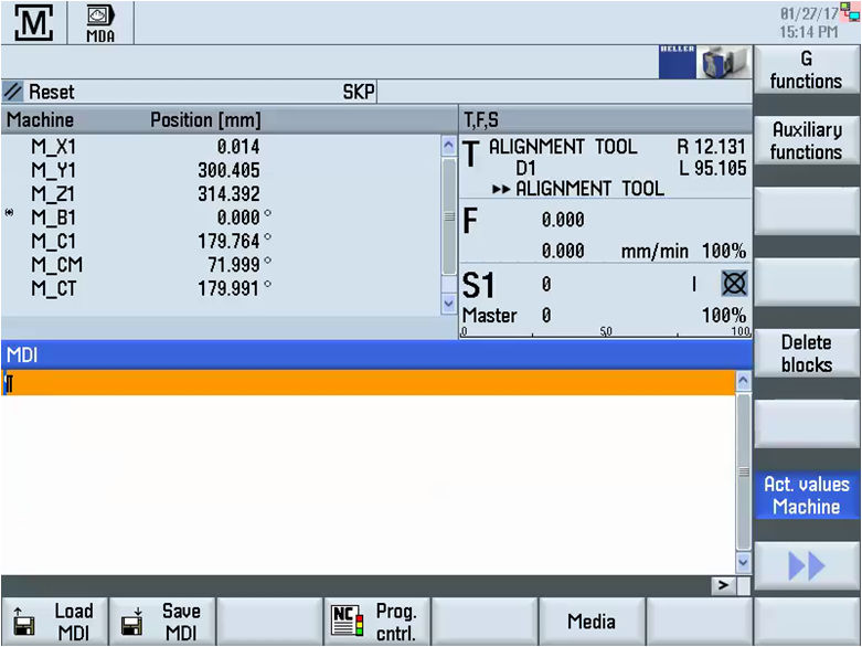
Turn feedrate off, so you can manually rotate spindle. Use square to align spindle. Step 20:Next set shift position for 4:1 to 1:1 Step 21:In MDA Step 22:In MDA: Step 23:Test Program
In MDA: Step 24:Correct if necessary. For example when you rotate the spindle to zero and it reads 359.497, you must subtract 360.000 - 359.497 = 0.503 and add 0.503 to the value in 34100[0] or [1]. |
|||||||||||||||||||||||||||||||||||||||||

