Replacing drive motor
Parts List
Reference Files
Tools Required
Torque Chart
Step 1: ECPL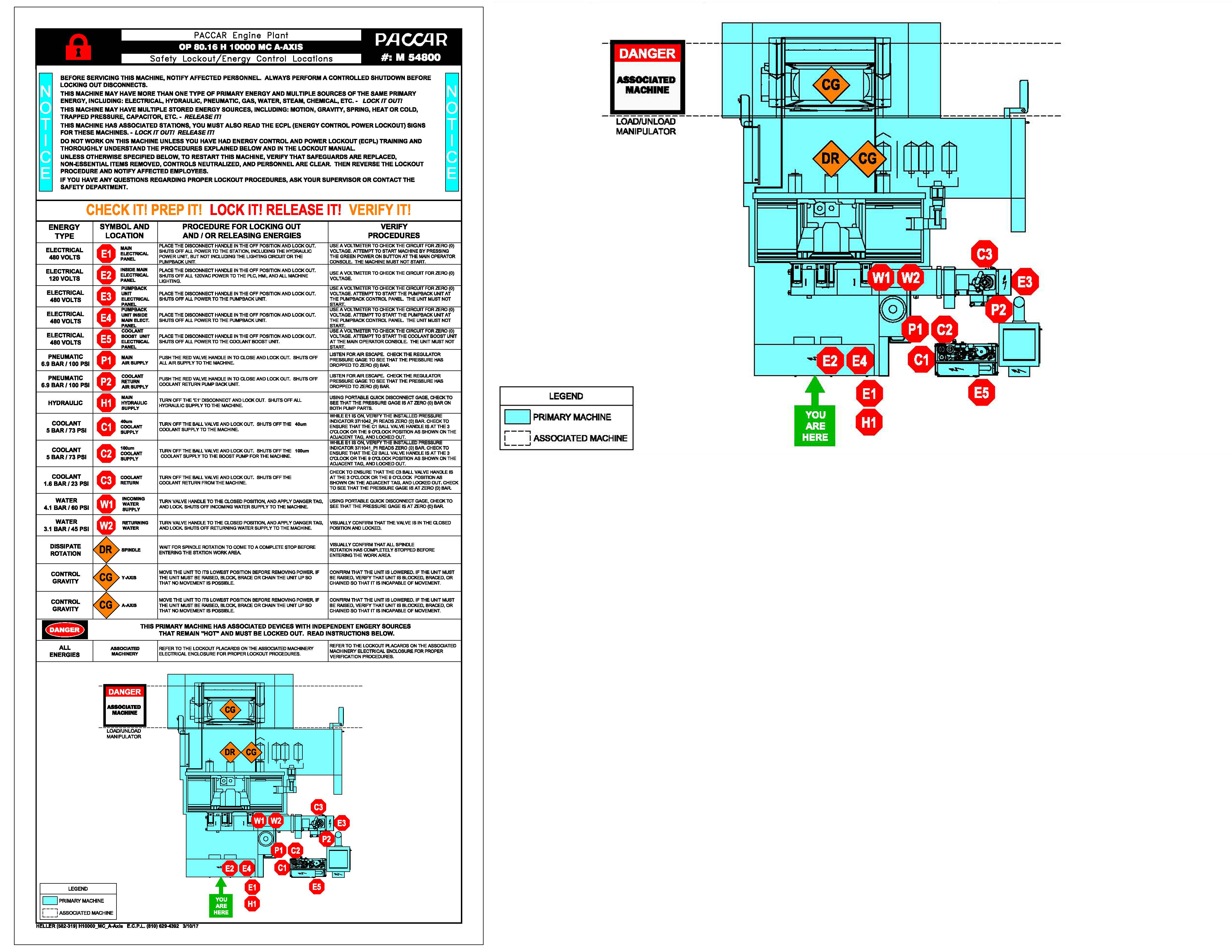
Step 2: Jog Z-Axis in Positive DirectionStep 3: Open Work Area Safety Door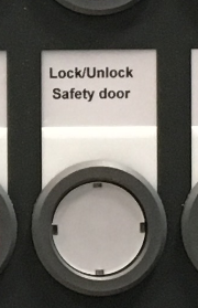
Step 4: Remove Z-Axis Concertina CoverStep 5: Loosen Belt Tension NutStep 6: Disconnect Motor Cables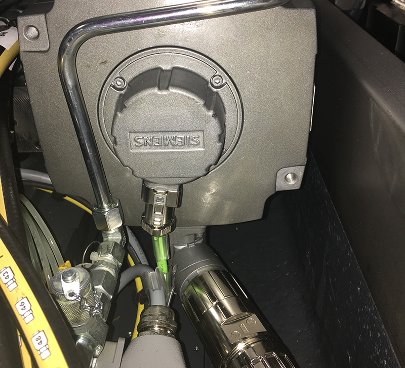
Step 7: Disconnect Motor Lines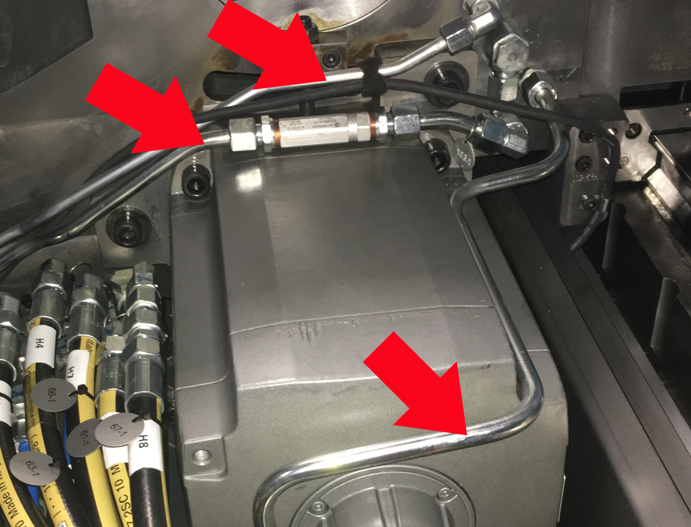
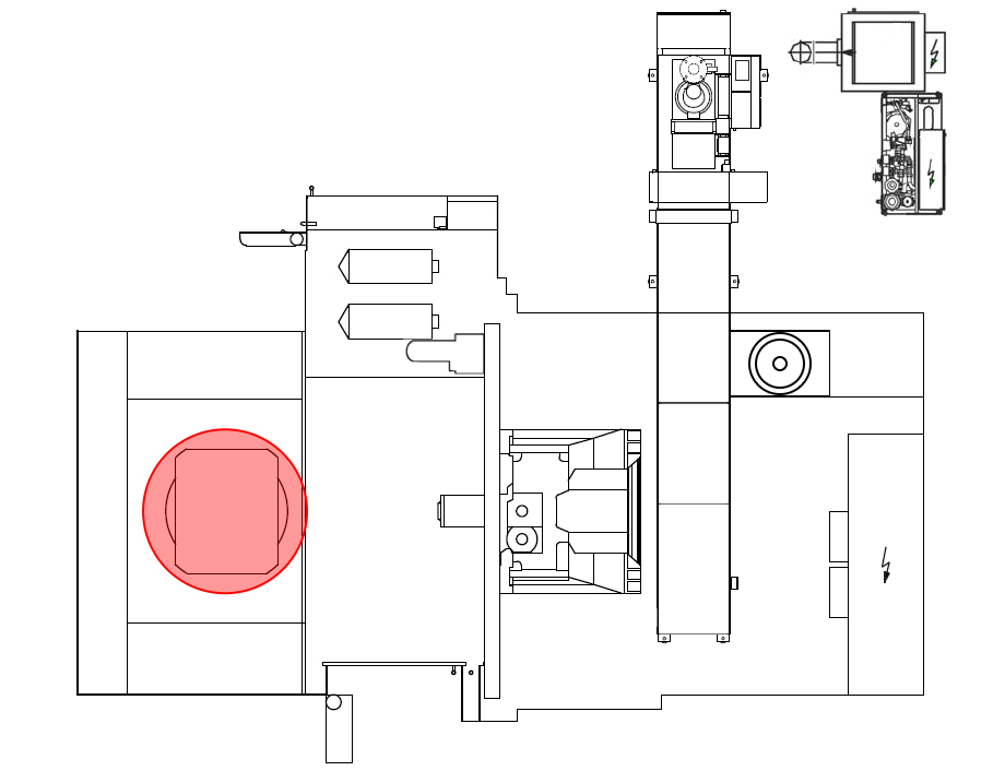
Step 8: Loosen Motor Housing ScrewsStep 9: Remove Motor ScrewsStep 10: Remove Motor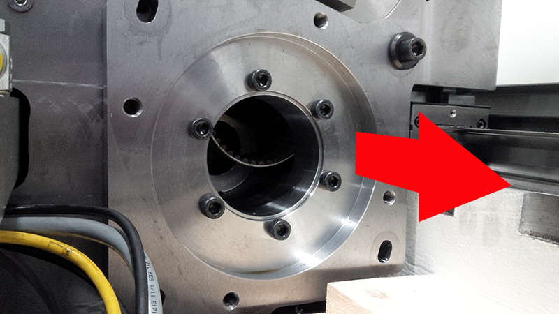
Step 11: Remove Belt Access Plate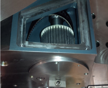
Step 12: Measure Motor Flange / Coupling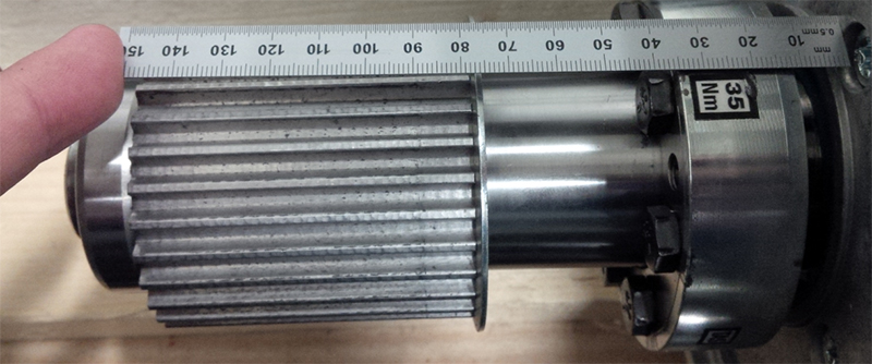
Step 13: Loosen BoltsStep 14: Separate CouplingStep 15: Install Coupling on New MotorStep 16: Measure Motor Flange / Coupling
Step 17: Install Bolts into CouplingStep 18: Secure Motor with Assist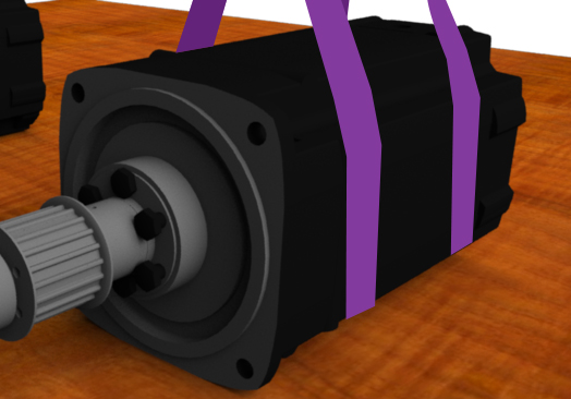
Step 19: Install Motor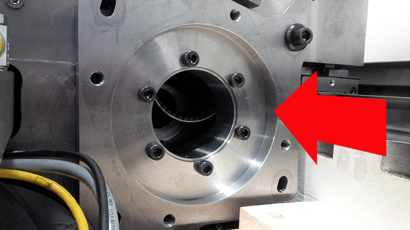
Step 20: Install Motor Screws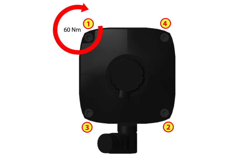
Step 21: Install Belt Tension NutStep 22: Tighten Motor Housing ScrewsStep 23: Reinstall Belt Access Plate
Step 24: Reconnect Motor Cables
Step 25: Reconnect Motor Lines
Step 26: Reinstall Concertina CoverStep 27: Close Work Area Safety Door
Step 28: ECPL
|
|||||||||||||||||||||||||||||||||||||||||||||||||||||||