Determine Tool Change Position
Reference Files
Tools Required
Torque Chart

The tool change positions are determined using two 3-piece tool changer alignment tools. Each alignment tool consists of the tool holder, gripper bushing and alignment arbor. The tool holders are inserted into the cartridge which is located in the provisional place and the empty spindle. The gripper bushings are inserted into gripper 1 and gripper 2. The alignment arbors are then used to determine the correct positions of the provisional place cartridge and the tool change positions of the X and Y axis. The positions are correctly aligned when the alignment arbor slides freely into the tool holders located in the spindle and provisional place. 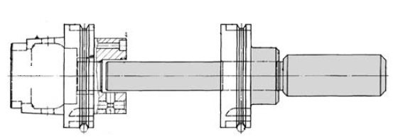
Step 1: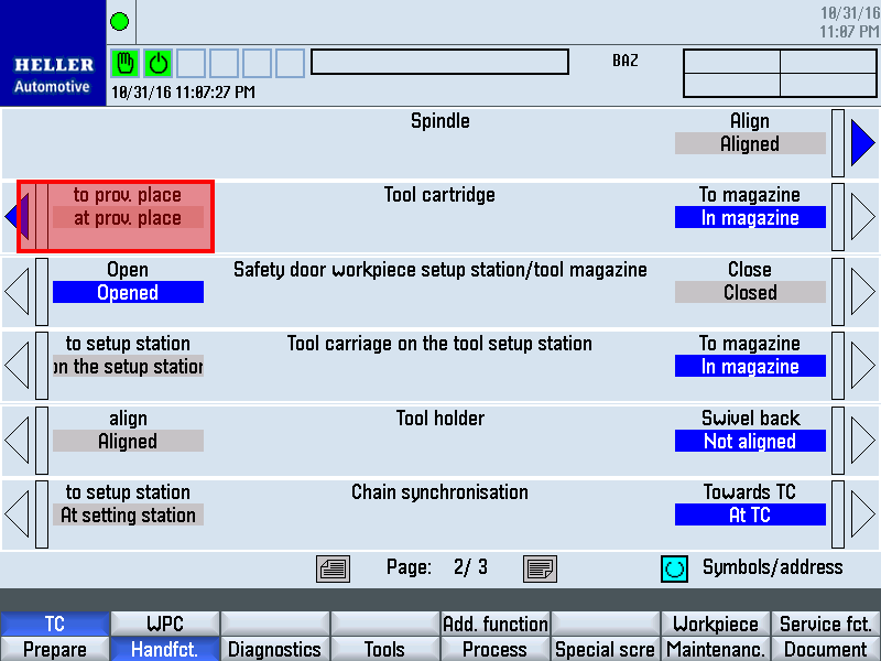
Close the operator door. In the HMI screen > hand functions > TC page down to page two. Find the "Tool cartridge" line Press the left side vertical softkey "to prov. place" to advance an empty tool pocket into the provisional place. Step 2: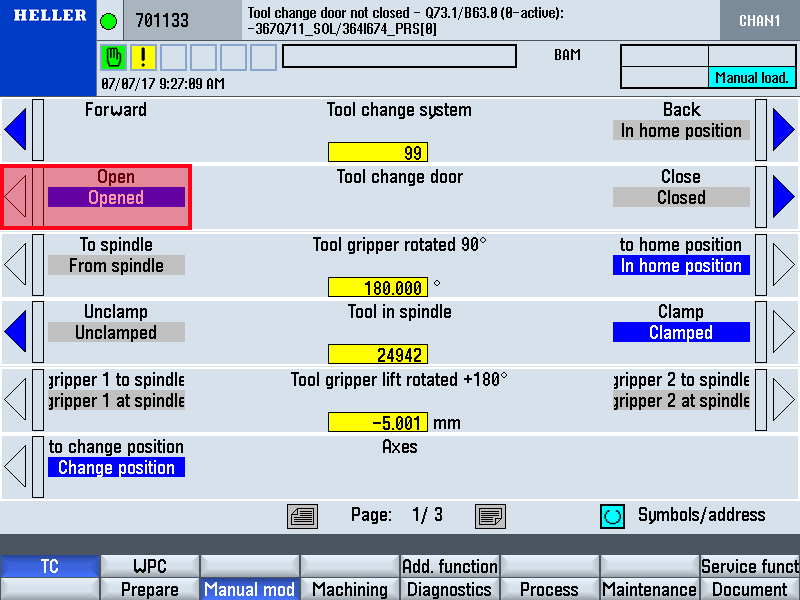
Open the tool changer door. Rotate the CT axis so it is in the horizontal position. Step 3: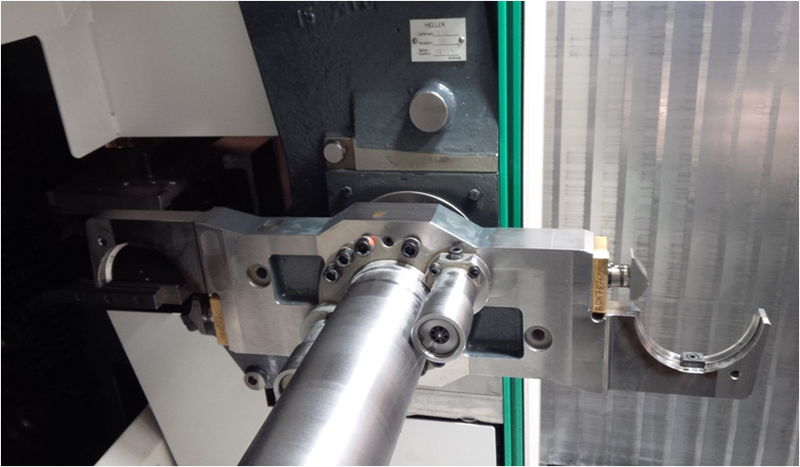
Insert the second piece of the setup tool into the tool griper so there is one in each side of the gripper Step 4: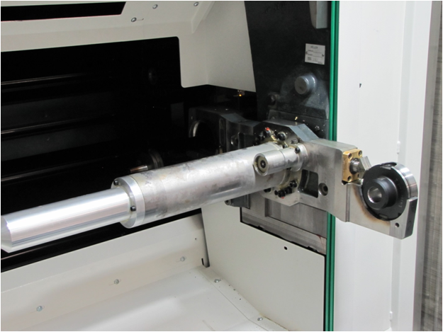
Jog the ZT minus direction so that there is clearance for the spindle with the HSK portion of the setup tool to fit behind the griper holding the setup tool In the HMI screen > hand functions > TC "page one" find the "Axis" line Press the left hand vertical softkey "change position" to jog the axis to the current tool change positions. Making sure there is clearance to avoid collision. Step 5: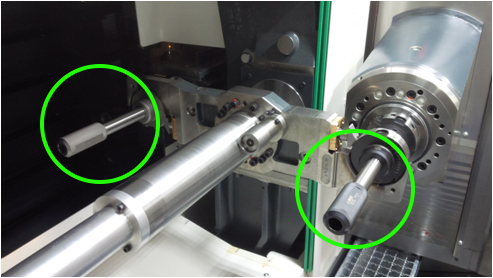
Open the operator door. And insert the shaft portion of the setup tool through the two pieces of the setup tool in the spindle and the gripper arm
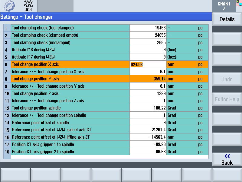
If the shaft does not freely and smoothly slide through the two pieces then incrementally jog the X and/or Y axis plus or minus so that a nice fit is achieved. Step 6:Once the shaft slides has a nice fit sliding through the two pieces of the set up tool note the X and Y axis positions Step 7:On the machine press the HMI key and then the > key press the settings key. Cursor down to highlight the Tool changer line and press the open key. Find the tool change positions X axis and the Tool change positions Y axis lines and type in the new values of the current machine positions. And press the input key 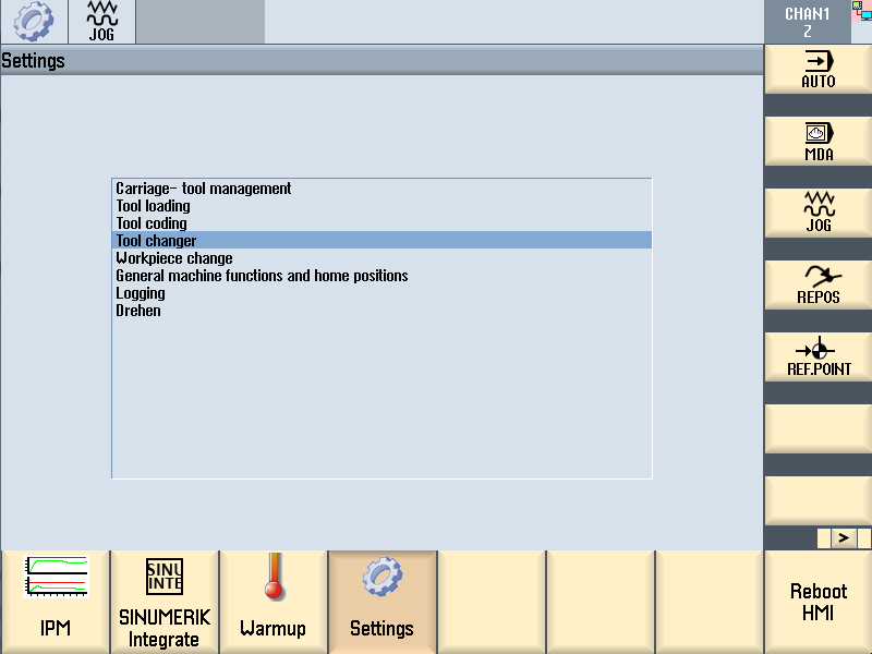
Step 8:
Remove the shaft portions of the set up tools Jog the x axis away from the gripper unclamp the spindle and remove the tool from the spindle and remove the tool from the pocket in on the magazine side. Step 9:
Jog the ZT axis in the plus direction to compress the plungers on the back side of the tool arm to unlock the tool arm finger and remove the setup tools from both sides of the gripper. Step 10: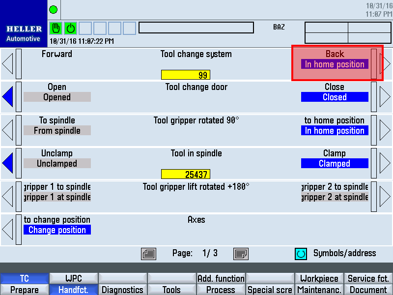
Move the tool change system to home position. Perform an NCK reset and then create an NC series archive to save all data. |
|||||||||||||||||||||||||||||||||||