Replace measuring system
Parts List
Reference Files
Tools Required
Torque Chart
Step 1: ECPL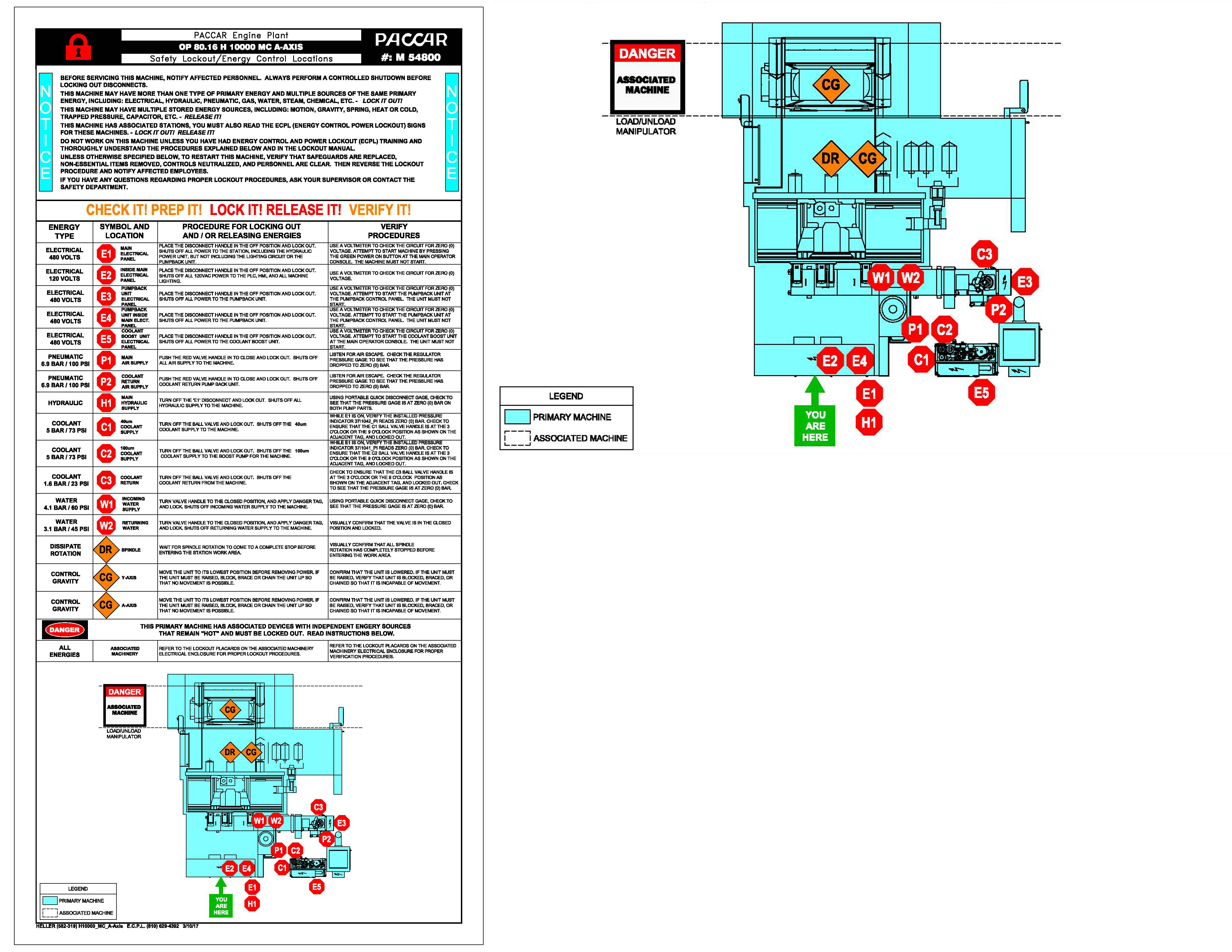
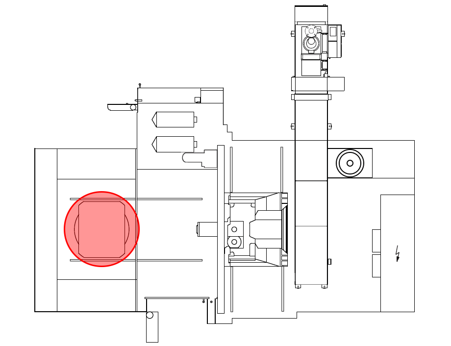
Step 2: Jog Z-Axis Towards Machining UnitStep 3: Open Work Area Safety Door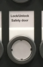
Step 4: Remove BoltsStep 5: Attach Lift Device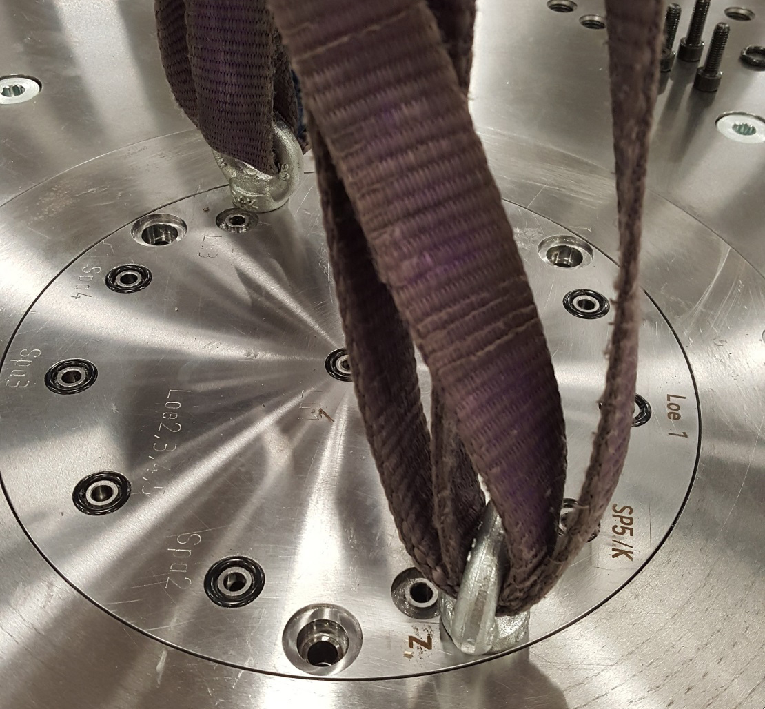
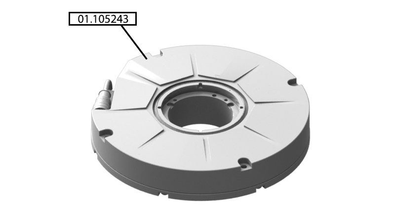
Step 6: Remove Distributor ShaftStep 7: Remove Caps, Screws, and Dowel PinStep 8: Remove Top Cover and CollarStep 9: Remove Encoder SpacerStep 10: Remove Cable and Air Line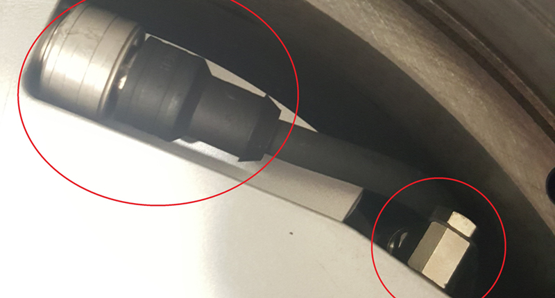
Step 11: Remove Screws from ScaleStep 12: Remove ScaleStep 13: Install ScaleStep 14: Install Screws into ScaleStep 15: Install Cable and Air Line
Step 16: Insert Encoder Spacer "Be sure to line up holes on the spacer"Step 17: Install Top Cover and CollarStep 18: Install Caps, Screws, and Dowel PinsStep 19: Lubricate Distributor Shaft
Step 20: Install Distributor ShaftStep 21: Remove Lift Device
Step 22: Install BoltsStep 23: Close Work Area Safety Door
Step 24: ECPL
|
|||||||||||||||||||||||||||||||||||||||||||||||||||||||