Spindle Motor Replacement
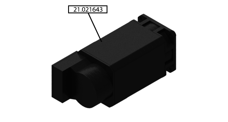
Parts List
Reference Files
Tools Required
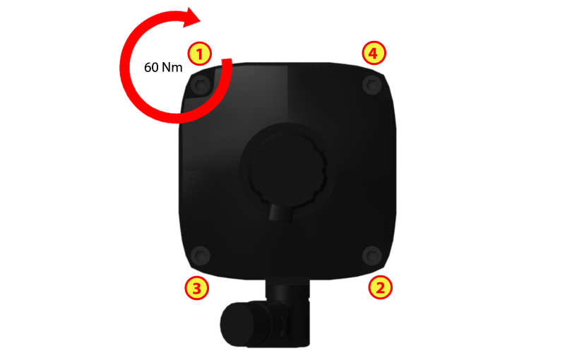
Torque Chart
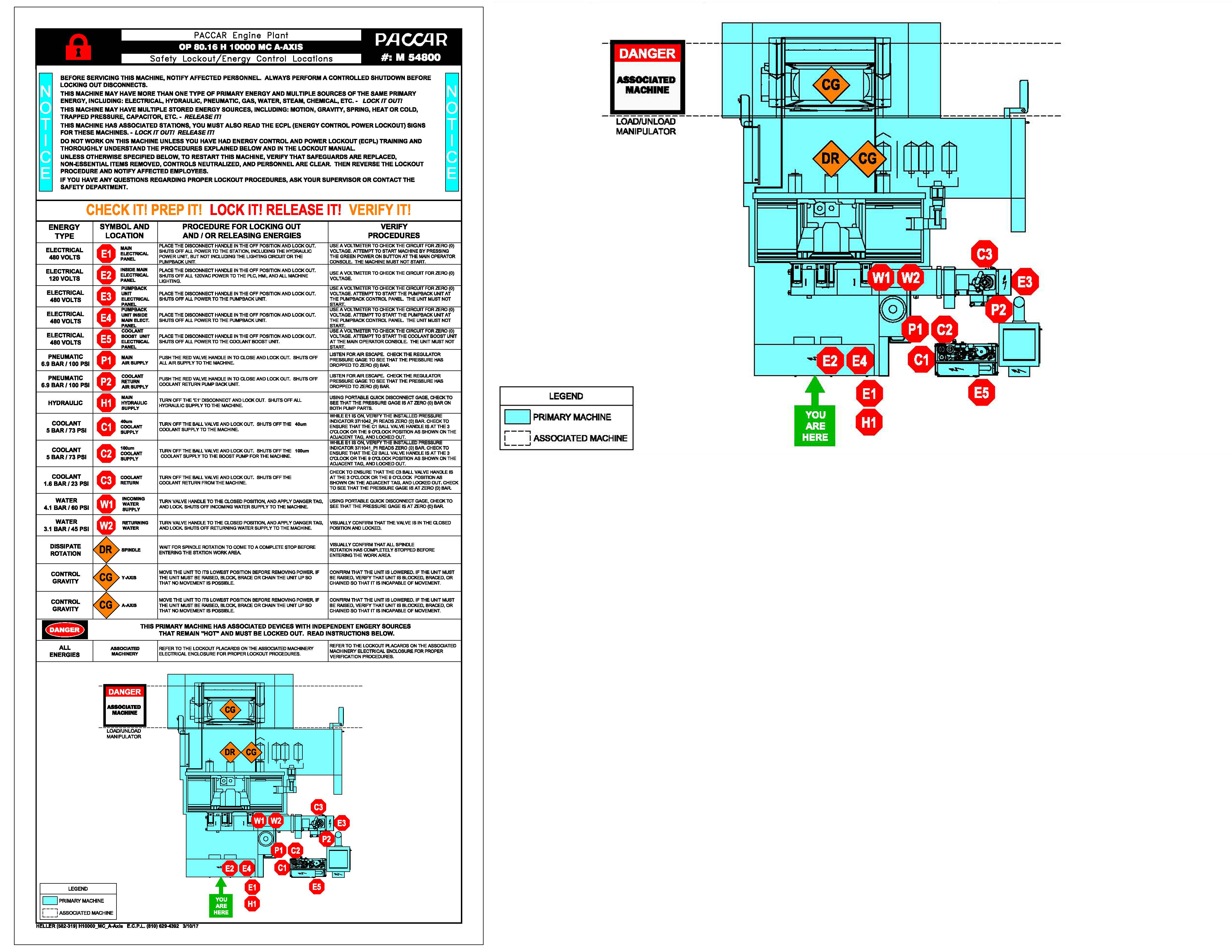
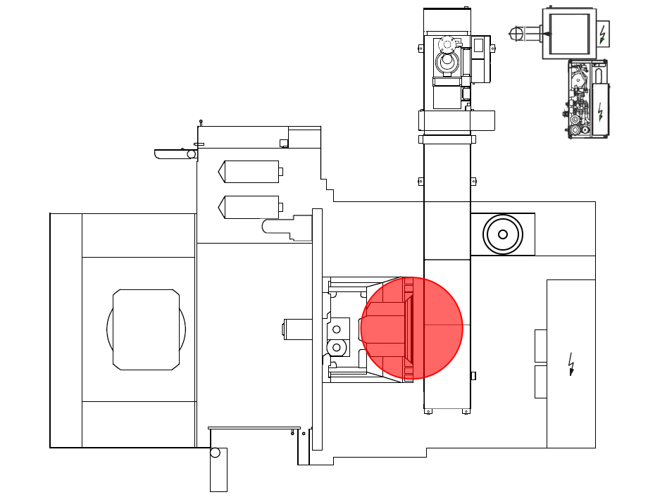
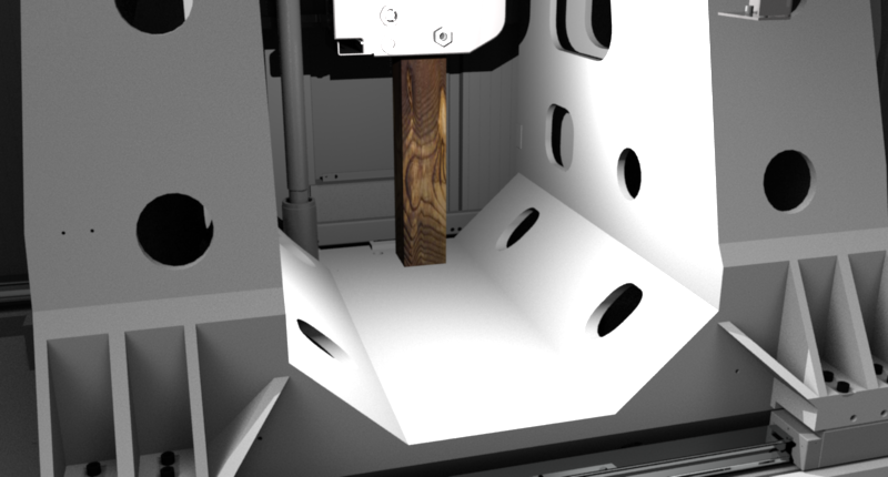
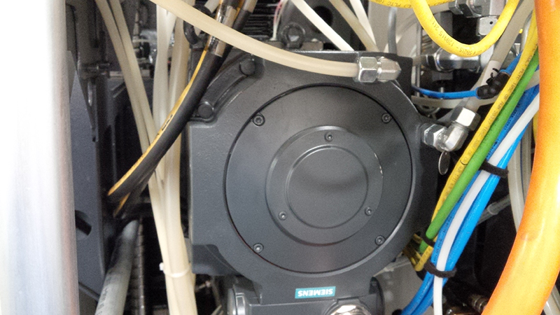
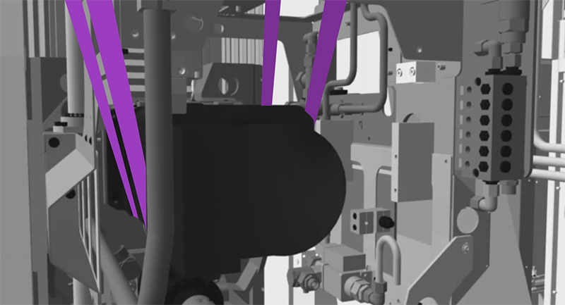
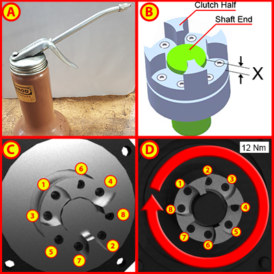
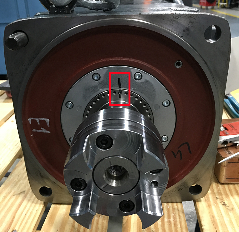
Step 1: ECPLStep 2: Position Axis to CenterStep 3: Open Work Area Safety DoorStep 4: Secure Machining UnitStep 5: Align Gear Unit to Shift Position"See procedure: Gear Unit Reference Points" Step 6: Remove Services from MotorStep 7: Attach Lift DeviceStep 8: Remove Screws from MotorStep 9: Remove MotorStep 10: Remove Absorbing InsertStep 11: Remove Screws from Coupling HalfStep 12: Insert Jack ScrewsStep 13: Remove CouplingStep 14: Lubricate Motor / Measure Coupling / Install Screws / TorqueStep 15: Install CouplingStep 16: Install Coupling ScrewsStep 17: Install Absorbing InsertStep 18: Check Zero Position (two markings need to match up) and Mount MotorStep 19: Insert Motor ScrewsStep 20: Install Services to MotorStep 21: Align Gear Unit To Locked PositionStep 22: Unblock Machining UnitStep 23: Detach Lift DeviceStep 24: Close Work Area Safety DoorStep 25: ECPLStep 26: Verify "0" Position |
|||||||||||||||||||||||||||||||||||||||||||||||||||||||
