|
Operator Interface (HMI) Panel
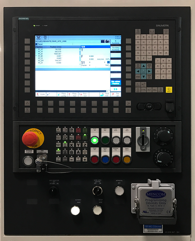
The Operator Interface (HMI) Panel module, also referred to as the Main Operating Panel (MOP), contains electrical and electronic devices that make up the control system for the H10000 Series.
These devices include the system controls and the pushbutton controls.
For detailed information on this panel, refer to Detailed Panel Descriptions.
The Main Operating Panel contains most of the controls used by the operator and other users to control machine operation. This module functions as a reference for the operator controls found on the cabinet panels.
The pushbuttons, selector switches and lamps are located below the operator interface display on the Main Operating Panel.
Click the panel buttons to view component descriptions
Operating panel for control functions
- Area changeover, menu control
- Alphanumeric character entry, cursor movement
- Connection for full keyboard
Machine control panel
- EMERGENCY STOP handheld operating unit
- Operating modes, program control, safety doors
- Motors on/off, start/stop machine, home position
Operating panel for machine functions
- Preselect "Open safety door", socket/interface
 |
| The vertical softkeys are assigned functions to the currently selected horizontal softkey. Pressing a vertical softkey calls the function. The assignment of the vertical softkey bar can change again if further sub-functions can be selected under a function. |
 |
A function is assigned to the softkeys via a menu bar on the screen.
- With the horizontal softkeys any main menu in further main menu levels can be reached. For each horizontal menu point there is an associated vertical menu bar/softkey assignment.
|
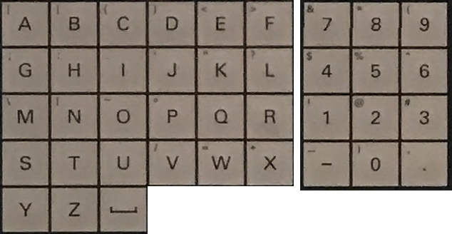
These dual-function keys are used for data entry and modification.
- Numeric keys to input numbers, directly accessible.
- Alphabetic keys to input text, accessible via Shift.
 |
Alarm cancel - Pressing the Alarm acknowledgement key clears the error. |
 |
Information - Pressing the Informationkey in the Diagnostics/Alarms main menu automatically calls up the Help function. |
 |
Channel changeover - Pressing the Channel changeover key switches the screen to an alternative channel. |
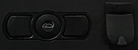
Mouse Control - the middle ball controls the motion of the mouse and the buttons on either side of the ball are the respective left and right mouse.
USB Connection - is used for connecting external devices, such as a laptop or flash drive, to the Operator Interface Panel.
 |
Automatic - Use the key to change to "Automatic" NC mode, also frequently known as "AUTO". |
 |
MDA - Use the key to change to the "MDA" operating mode, also known as "MDI (Manual Data Input)". |
 |
JOG - Use the key to change to the "JOG" NC operating mode, also known as Jogging, Setup mode or Inching mode. |
 |
Ref Point - The machine function "Referencing" is called up with REF. The NC mode JOG is essential here. |
 |
Inc Var - With the INC function (incremental dimension), the preselected axis is moved in fixed increments in the appropriate direction in manual mode whenever a direction key is pressed. |
 |
Reset -
- Processing of the current part program is aborted.
- Messages from monitoring are deleted (except for acknowledge alarm, POWER ON and NC Start alarms).
- The channel is moved to the "Reset" state, meaning that:
- The NC control remains synchronous with the machine.
- The control is in the default setting and is ready for a new program sequence.
|
 |
Rapid Traverse Overlay - The Rapid traverse overlay key substitutes rapid traverse for the programmed feed rate. |
 |
NC Start - When the NC start key is pressed, the selected part program is started with the current NC block and the associated LED illuminates. |
 |
NC Stop - When the NC stop key is pressed, the current part program is stopped and the associated LED illuminates. |
 |
Single block - This function offers the possibility of processing a part program NC block by NC block. The "Single Block" function is activated in the "Automatic" or "MDA" NC mode. If "Single Block" is activated, the associated LED on the machine control panel comes on. |
 |
Feed Start - The part program is resumed in the current block, the feed is ramped up to the value specified by the program. |
 |
Feed Stop - This stops the running of the current program, axis drives are brought to a standstill. |
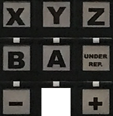
Axes keys - The Axes keys are used to select a NC axis that is to be traversed in manual mode.
The following keys are available for directly selecting the main axes.
| X |
M_X1 |
Column (horizontal axis) |
x |
| Y |
M_Y1 |
Column (vertical axis) |
x |
| Z |
M_Z1 |
Z slide with A/B axis |
x |
| B |
M_B1 |
Rotary table |
- |
| C |
M_C1 |
Spindle |
x |
Direction keys plus/minus - Direction key + or Direction key - move the axis preselected using the Axis key until the Direction key + and Direction key - are released.
 |
Next Axes - The Next Axes key opens a dialogue window from which other NC axes of the machine can be selected. The selected NC axis is activated for manual mode as soon as the selection is acknowledged with the Enter key. |
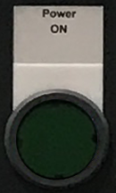 |
Power On - The media to the machine are switched on using the Power On key. Precondition:
- The machine has been switched on at the main switch. Control run-up is finished.
- EMERGENCY STOP is unlocked.
Status display:
- The lamp flashes when the function can be selected.
- The lamp remains lit constantly when all media are switched on.
|
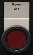 |
Power Off - The media and the load voltage for the machine are switched off using the Power Off key.
|
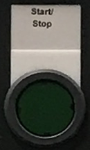 |
Start/Stop - The Start/Step key is used to start processes in dependence of the selected machine operating mode "OP Auto" or "Single Cycle" or "Single Step".
- The machine sequence is started in machine operating modes "OP Auto" and "Single Cycle".
- The next machining step is initiated in machine operating mode "Single Step".
In principle, the following preconditions must be met when starting sequences:
- EMERGENCY STOP switch unlocked.
- Media switched on.
- Safety doors locked
The key lamp identifies the statuses:
- Lamp on: Machine start is active.
- Lamp blinks: machine start initiated but not yet active.
|
 |
Cancel Next Cycle - The Stop at end of cycle key ends fully-automatic operation of the machine: The current workpiece is completed and the machine then stops without transporting the workpiece any further.
- The machine stops.
- Spindle and all movements are brought to a halt.
- The load voltage remains switched on.
The key lamp identifies the statuses:
- Lamp on: "Stop at end of cycle" has been reached. The machine is stationary, spindle and all movements have been halted. The lamp goes out if the machine is re-started or the operating mode is changed.
- Lamp flashing: Function selected although "Stop at end of cycle" has not yet been reached.
|
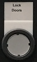 |
Lock Doors - The Lock safety door key is used to unlock or lock all safety doors of the affected control area. The lamp identifies different statuses:
- Lamp on: Safety doors to the affected control area are unlocked.
- Lamp flashing: Function requested although not all safety doors are unlocked.
- Lamp off: safety doors to the affected control area are locked.
Precondition:
- The "NC Stop" function must be active.
|
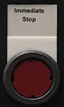 |
Immediate Stop - Sequences within the respective control area are stopped with the Immediate stop key, regardless of the selected operating mode.
- Spindles and all movements are brought to a halt immediately.
- The load voltage remains switched on.
The key lamp identifies the statuses:
- Lamp on: the machine is stationary.
- Lamp blinks: function has been selected although not all switch-off routines are finished.
|
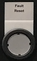 |
Fault Reset - If the lamp on the Fault Reset key flashes, a machine alarm is queued.
To reset the machine alarm (after correcting the cause!), press the Fault Reset key. The lamp goes out. |
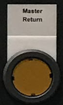 |
Master Return -The Home position key triggers movements only on the machine on which the key was pressed. When the key is pressed, the following movements are triggered in sequence:
- NC stop is triggered.
- Reset is triggered.
- The tool changer moves to its home position. After leaving the release position of the tool gripper, it moves forwards to its home position. Before this position it moves backwards to its home position.
- The machining axes move to their home position as programmed in the "Home" jump marker.
|
- The LED flashes whilst the home position is being approached.
- The LED comes on when the home position is reached.
|
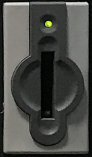 |
Electronic Key - These access levels are enabled by the Electronic Key System (EKS) in the machine control panel and the corresponding electronic keys. The colour-coded keys contain the access codes for the entitled group of persons concerned. |
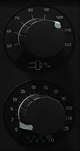 |
Feed Override - The Feed override is a rotary switch which is used to adjust the feed rate of an axis between 0 (no motion) and 120% of the programmed feed rate.
The switch can be used in both manual and automatic modes. It is used to limit the feed rate for greater accuracy during manual positioning. It is also useful when commissioning new or modified programs in Single Block mode.
During normal operation, this switch should be set to 100%.
|
Spindle Override - The Spindle override switch is a rotary switch used to vary the spindle rotation speed between 50 and 120% of the programmed setting. |
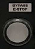 |
Bypass E-Stop - Key to bypass the emergency stop device, if the Approval unit or the Handheld terminal is to be connected and the bypass socket has been removed. A machining program that is already running is not interrupted when the button is pushed. The Bypass E-Stop key can be released as soon as the approval unit/handheld operating unit or bypass connector is connected. |
 |
HT Connection - Connection for the approval unit or for the handheld terminal. Normally, the connection is closed with the bridge connector. |
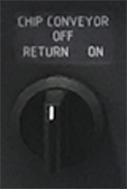 |
Chip transport - The switch actuates the conveyor helixes in the machine bed. The switch has 3 positions from which the following functions can be executed:
- Conveyor helixes (forward)
- Conveyor helixes off
- Conveyor helixes in sensing mode so that it can move the helix free in the event of a chip build-up.
|
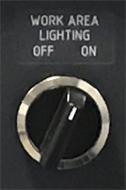 |
Work area lighting - Switches the work area lighting on and off. |
 |
Approval Key - "Traverse with safety door open" function: In conjunction with special operating modes 2 and 3, the Approval key key permits axis movements and spindle rotations with the safety door open. |
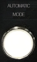 |
Automatic Mode - Pressing the AUTOMATIC MODE illuminated pushbutton activates the normal "AUTOMATIC" mode if the key switch is set to the right position. The associated key lamp now lights up.
Permissible functions:
- Traversing with work area safety door closed.
- Fully-automatic machining of workpieces in production mode.
- Automatic workpiece change (machines in linkage).
|
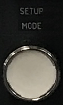 |
Setup Mode - Pressing the SETUP MODE illuminated pushbutton activates the special "SETUP" mode if the key switch is set to the right position.The associated key lamp now lights up.
Permissible functions:
- Traversing at reduced speed when the work area safety door is open.
- Use of mobile handheld operating unit.
- Axis movement in inching mode (JOG) continuous or step by step.
|
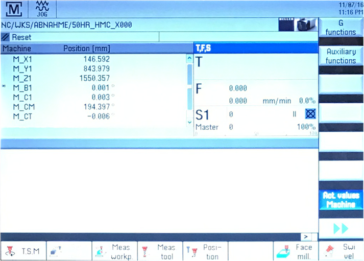
This is the screen used to display all machine data and is used in conjunction with the Horizontal and Vertical softkeys.
 |
Emergency Stop Button - An emergency stop brings all drives to a standstill with the greatest possible braking torque. This will cause all motion on the machine to stop IMMEDIATELY. |
|
