Fixture Management System

Function

In manual mode, the "fixture management system" controls workpiece machining.

An unmachined part is moved from the loading or setting station to the machining position near to the spindle. The assigned machining program is automatically selected and started. The setter defines the assignment in the "Fixture management system" in a preceding operating step. The required programs must be loaded into the Programs area of the Sinumerik control system.

In linked mode, the automation system controls the machining of the workpiece (loader interface). During each loading operation, the workpiece data for the unmachined part in the loader are transferred to the machine and used.

  • Wp type
  • Machining program

Calling up the fixture management system

Step 1:

Preconditions:

  • Control run up.
  • Safety doors closed and locked.

With Data menu key call up the basic menu on the main operator panel.
Press the "Fixture" softkey.

Step 2:

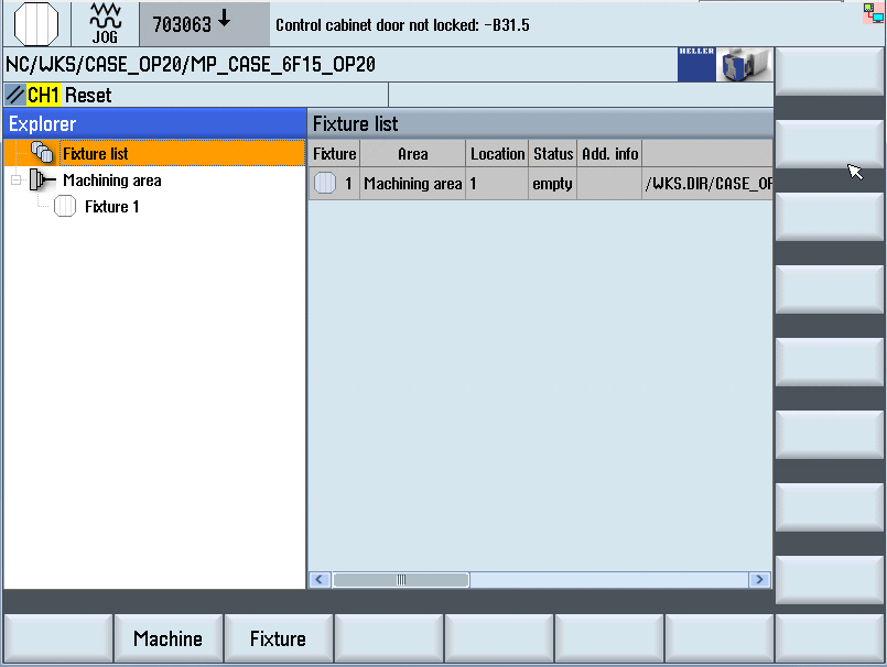
The basic display of the fixture management system is opened. The cursor is located on the "Fixture list" symbol. The fixture list is shown on the right-hand side.

Step 3:

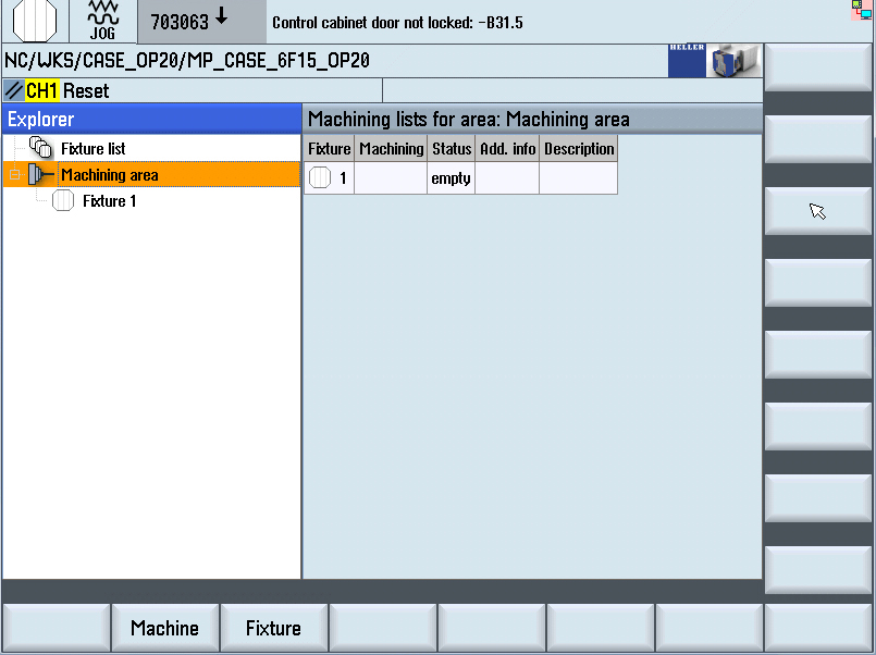
In Explorer view, move cursor down one level. The cursor is located on the "Work area" symbol. The list of machining operations created for the work area are shown on the right-hand side of the screen.

Step 4:

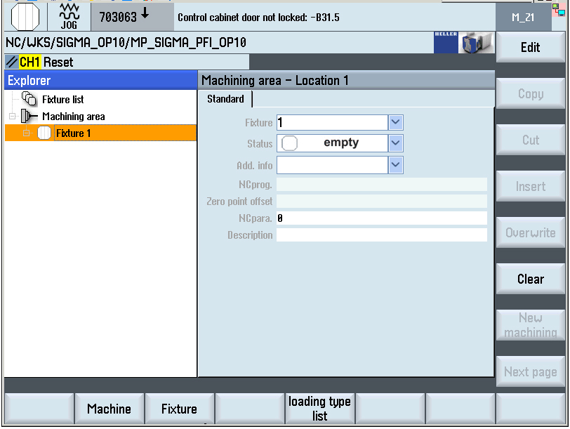
In Explorer view, move cursor down one level. The cursor is located on the "Fixture" symbol. The data for the fixture in the work area appear on the right side.

  • Fixture number: 1
  • Fixture status: empty

Defining the fixture status

Caution:
Mechanical changeover:

Before operating the machine with fixture no. 2 (no. 3 etc.), the respective fixture must be physically present in the machine. A fixture change might have to be carried out first.

Change-over by data: During system setup, basic data can be used. Basic data includes the following input fields:

  • Fixture number
  • Fixture status
  • Machining program (file)

Selecting fixture no. 2

Step 1:

Preconditions:

  • The basic screen of the fixture management system is displayed.
  • Fixture no. 1 created by data.

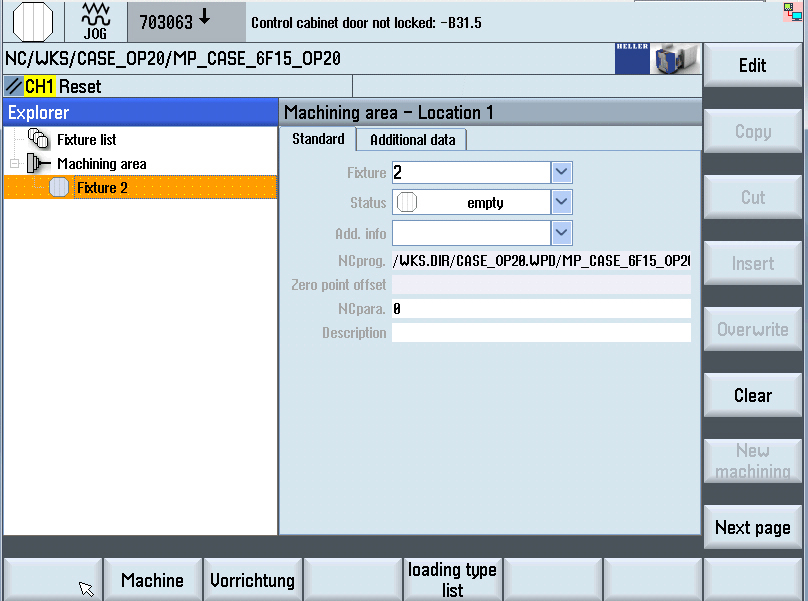
In the Explorer View, select the empty fixture location in the machine using the Cursor keys (work area - location 1).
The data for old fixture no. 1 appear on the right side.
When setting up the new fixture, the basic data must be entered. Basic data includes the following input fields: Pallet number of pallet

  • Fixture - Fixture number = 2
  • Status - Fixture status = empty

Step 2:

Press the right softkey "Edit".
The input fields are ready for data input.
The "Fixture" field is ready to accept input (highlighted yellow).
Open "Fixture" field and select the fixture number 2 using the cursor keys.

Step 3:

Enter fixture status: empty (white symbol)
Press the "Save" softkey.
The data are saved.
Fixture no. 2 is created in the system and active.

Selecting fixture no. 3 etc

Step 1:

Preconditions:

  • The basic screen of the fixture management system is displayed.
  • Fixture no. 2 created by data.

Procedure:

  • See previous procedure for fixture 1 (2) accordingly.

Defining workpiece status

The fixture/workpiece status is defined on the "Standard" tab of the "Work area - Location 1" input screen.

The status is always pre-assigned with "raw".

Overview of workpiece statuses:

  • Empty: Status indicates an empty fixture that can be loaded with a new workpiece.
  • Raw: Status denotes a new workpiece that has been loaded. The workpiece is released for automatic machining with the "raw" status. If a workpiece is not enabled for automatic machining, you must modify the status manually.
  • Partially machined: Status denotes a workpiece that is currently being machined. The status can also be assigned to a workpiece outside the machine, for which the machining operation was aborted for some reason.
  • Finished: Status denotes a finish machined workpiece that is ready for collection.
  • Reject: Status indicates a NOK part that is also ready for collection.

Step 1:

The workpiece status is to be defined as "raw".

Precondition:

  • The empty fixture location (work area) is selected in the Explorer View.
  • The "Location 1" input screen is opened for entering data.

Press the right softkey "Edit".
The input fields are ready for data input.

Using the Cursor keys, select the "Status" input field.

Press the Insert key.
The selection menu opens.

Select the "raw" status using the Cursor keys.

Press the Enter key.
The "raw" entry is accepted into the input field.
The selection menu is closed.
Press "Overwrite" softkey to save the entry.

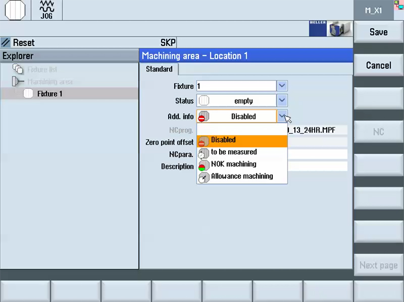
Specifying additional info

More additional info on the fixture and workpiece in the work area can be set using the selection list.

Step 1:

Precondition:

  • The fixture location (work area) is selected in the Explorer View..
  • The "Location 1" input screen is opened for entering data.

Using the Cursor keys, select the "Status" input field.
Press the Insert key.
The selection menu opens.

Step 2:

Possible additional info:

  • disabled: The fixture is defective and is no longer controlled by the loader. Functions such as clamp/unclamp as well as the workpiece location check are no longer executed.
  • to be measured: A finished part is to be transported to a measuring station following fault-free machining.
  • NOK Machining: A partially machined workpiece is to be transported to a measuring station. If the test result is positive, the machining of the workpiece can be finished after reloading.
  • Allowance machining: The workpiece is to be premachined as a first step.

Step 3:

Possible additional info:

  • Clamping Time (optional):
    If the "Hydraulic workpiece clamping" option is present and the "Clamping check" option is deselected or not present, the duration of the clamping process in seconds can be entered into the "Clamping time" field.

    If the "Clamping check" option is selected, the entered duration is used to runtime monitor the clamping check.

  • Unclamping Time (optional):
    If the "Hydraulic workpiece clamping" option is present and the "Unclamp check" option deselected, the duration of the clamping process in seconds can be entered into the "Unclamping time" field.

    If the "Unclamp check" option is selected, the entered duration is usd to runtime monitor the unclamping check.

  • Location Check:
    With a hydraulic loading station with integral location check option, the position of a workpiece (or several workpieces) in the mounting fixture can be checked.

  • Unclamp Check (optional):
    On a hydraulic setting station with integrated "Unclamp check" option, whether or not the workpiece clamping fixture has been fully unclamped before the workpiece is picked up from a loader, for example, can be checked.

Assigning NC-program to the fixture

In stand-alone mode, the workpiece type can be selected by selecting the corresponding NC program. There are several NCprograms (workpiece types) to choose from.

The transfer initiates a changeover by software in the control system (machining program, zero point offset etc.).

The directory and the NC program assigned to the clamping fixture are defined in the "NC Program" input field. The NC program in a program directory can be selected using an Explorer.

Step 1:

Precondition:

  • The empty fixture location (work area) is selected in the Explorer View.
  • The "Location 1" input screen is opened for entering data.

Press the right softkey "Edit".
The input fields are ready for data input.

Use the Cursor keys to select the "NC-Prog." input field.
Vertical softkeys for selecting the file directories are displayed.

Press the right softkey "NC".
A window for file selection is opened (Explorer tree).

Step 2:

If necessary open or close directory with the Enter.

Use the Cursor keys to select a program with ending ".MPF".

Files with a ".URF" extension must not be selected. These files are used for zero offset.

Press the "Use file" softkey.
The NC program is accepted into the input field.

The Explorer is closed.

Assigning NC programs from the loading type list

The loading type list enables you to create ("loading type) production jobs. One or several machining operations can be assigned for each loading type. You can assign an NC program to each machining operation.

An external loading system control requests a loading type from the loading type list. For this loading type, the data are transferred from the loading type list to the fixture management system.

Assigning a loading type to a fixture

Step 1:

Precondition:

  • Fixture management system opened.
  • The empty fixture location (work area) is selected in the Explorer View.
  • The "loading type list" softkey is displayed.

Use the Cursor keys to select the fixture to which a machining program is to be assigned.

Press the "Loading type list" softkey.
The loading type list is opened.

Step 2:

Use the Cursor keys to select the loading type which is to be assigned, for example:

  • loading type 1 or
  • loading type 2.

The symbol concerned is highlighted in the Explorer.
Press the vertical softkey "Assign type".
The loading type is transferred from the loading type list to the fixture management system.

  • The data not stored in the loading type list remain in the pallet management system.
  • The fixture status is set to "raw".
  • The additional info is cleared.
  • The loading type list is closed.