Tension Magazine ChainsInterval 5000 Hours Operating time Component Magazine chains To readjust the conveying station towards the tool changer place after clamping operation, the machine data has to be modified. You must hold the relevant access right. The control system accepts machine data input without confirmation. Overwritten data will be lost. Incorrect values can result in severe damage to the machine. Inputs take effect at different times according to level of effectiveness. Machine data must only be changed by specially trained personnel. Proceed as follows:
Oil can Precision torque wrench (width across flats 18 mm) For control functions, see machine operating instructions (BD). You will require the following functions:
Refer to the "SINUMERIK 840D sl - Operating Manual". Data backupFor additional information on data security, see the Operator's Manual for the Machine (BD), chapter entitled "Data security of the machine manufacturer's data". Data Backup ProcedureUnloading tool magazineObserve Chapter 4.2 "Special safety measures" before opening the guard panels and when entering or leaving the machine. Exercise extreme caution when working in the maintenance area with unsecured machining unit! Avoid working below the machining unit! Step 1: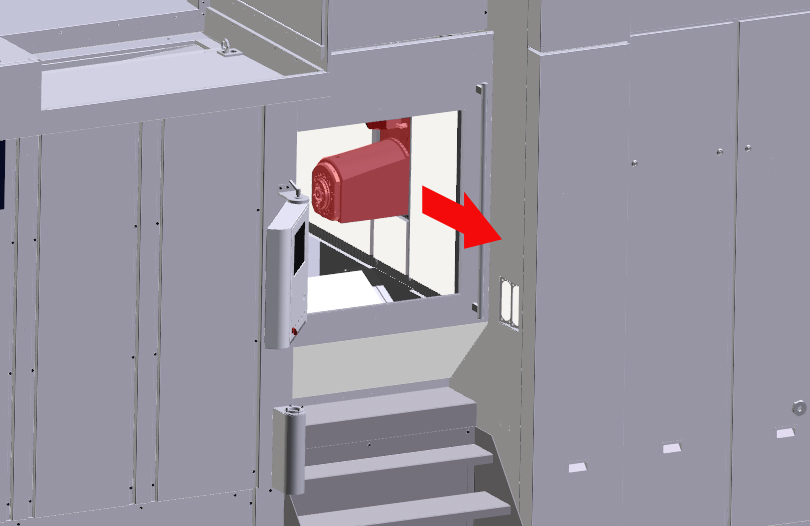
X-axis (frame) moved towards the work area safety door, so that the clamping device is accessible later. Step 2: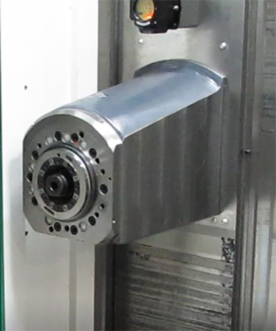
There should be no tool in the tool spindle. Step 3: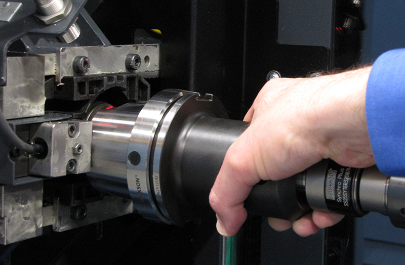
Remove all tools from the tool magazine. Step 4:Move magazine place 1 to the cartridge unloading position. Depending on the magazine size, the following magazine place is located at the tool setting station:
Step 5: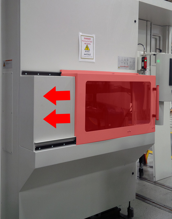
Unlock and open the tool loading station safety door Step 6: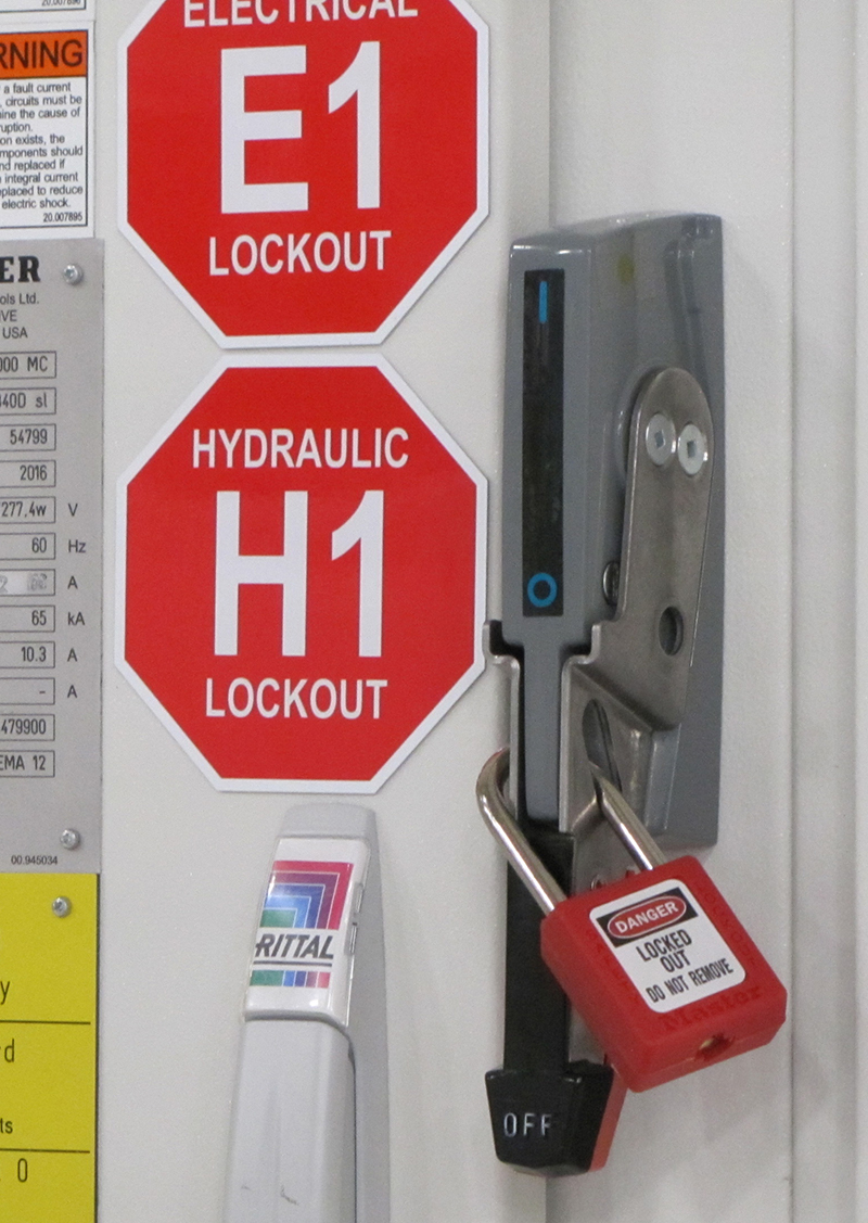
Switch off machine at main switch and secure against being switched on again. Step 7: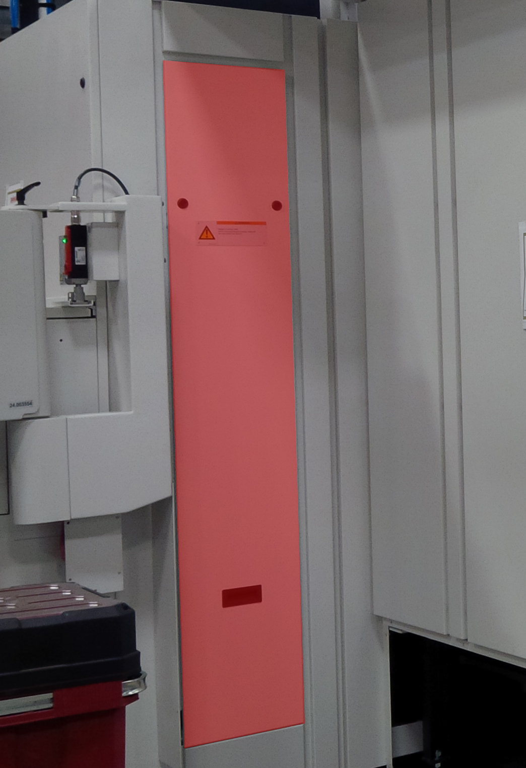
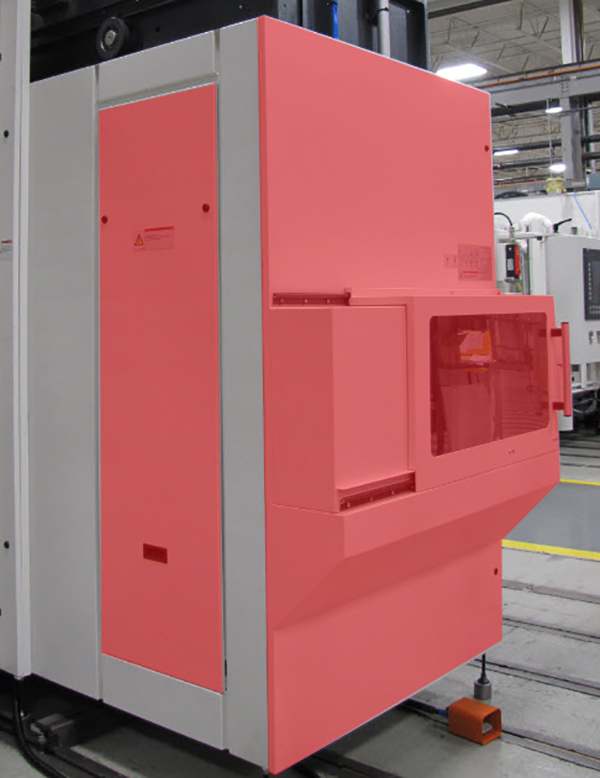
Open maintenance door of the tool magazine. For more information on how to open the maintenance door see: "Opening the chain magazine maintenance door" Step 8: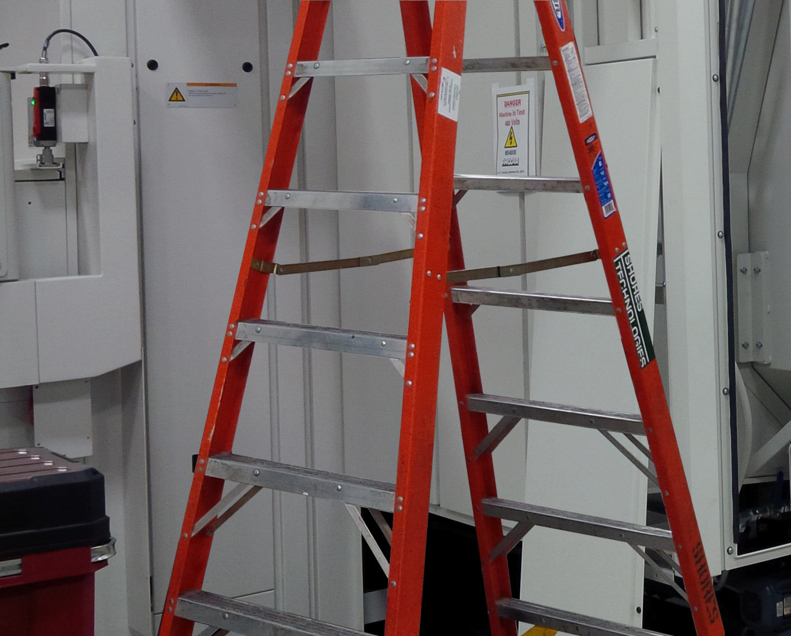
Position the ladder so that you can safely reach the cartrige unloading position. Step 9: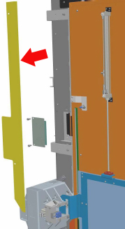
Remove guard panel. Step 10: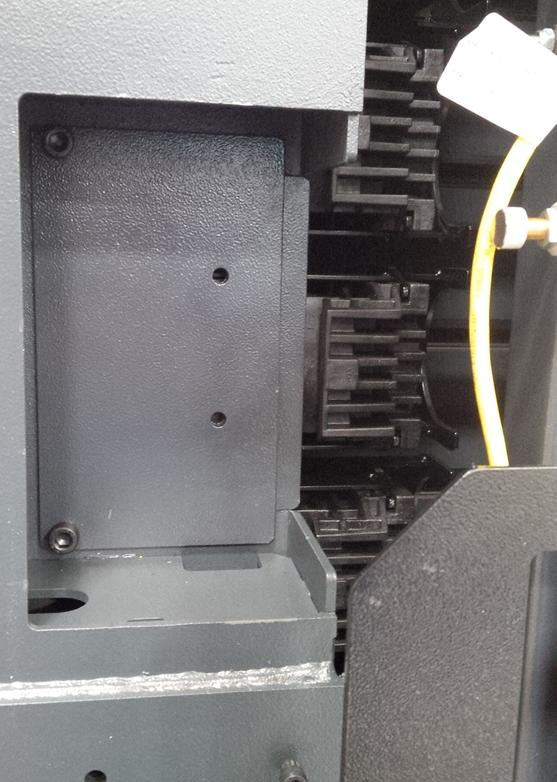
Remove cover (2 hexagon socket screws). Step 11: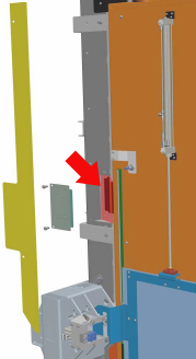
Remove tool cartridge. Make clamping devices accesibleProcedure Open maintenance openeing B and D. Tensioning procedureTwo screws fasten the guide frame to the plate. This ensures that the distance between the guide frame and the tool cartridges remains the same even after the magazine chains are tensioned. Do not slacken these two screws ! The tensioning device at both the drive side and the non-drive end must be adjusted by the same amount in order to preserve the alignment of the transmission shaft and the sprocket shaft. By the same token:
Step 1: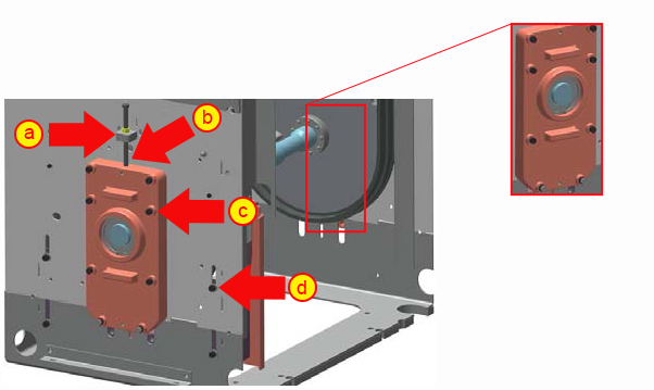
Prepare both ends for tensioning:
Ensure that the two guide frame fixing screws do not detach from the plate. Step 2: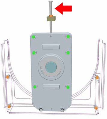
Using a torque wrench, tighten the two setscrews at the drive and non-drive ends:
Step 3: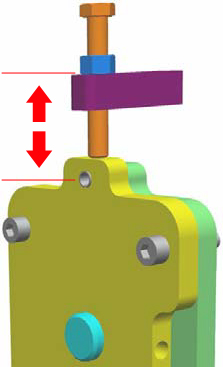
Ensure that the two tensioning distances are identical:
Step 4: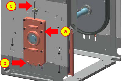
Secure the clamping fixtures:
Step 5:
Step 6:
Close tool magazine maintenance door. Step 7:
Close tool loading station safety door. Running in magazine chainsProcedure Turn on machine on at the main switch. Switch on motors. Run the tool magazine through its complete cycle at least twice in both directions. Align conveying station with tool changerThere is a structural offset of several millimetres between the two conveyor stations on the chain-type magazine (conveyor station to tool changer and conveyor station to tool setting station). The tool magazine is therefore fitted with two measuring systems: measuring system 1 is the motor encoder of the drive motor. This encoder synchronises the chain-type magazine with the tool changer. Measuring system 2 is a rotary encoder located above the tool setting station in the chain area. This encoder synchronises the chain-type magazine with the tool setting station. Normally, the control polls measuring system 1, so that the chaintype magazine is synchronised with the tool changer. The control switches to measuring system 2 only for transport of the cartridge between the tool loading position and conveying station. During switchover, the chain-type magazine moves up by the offset between the two conveying stations. In normal mode, this process is coupled to the activation of the alignment device, which fixes the tool holder on the conveying station to the tool setting station while the cartridge is being transported. For commissioning and service, chain synchronisation is provided as a separate individual function. Step 1: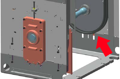
Magazine chains are retracted. Step 2: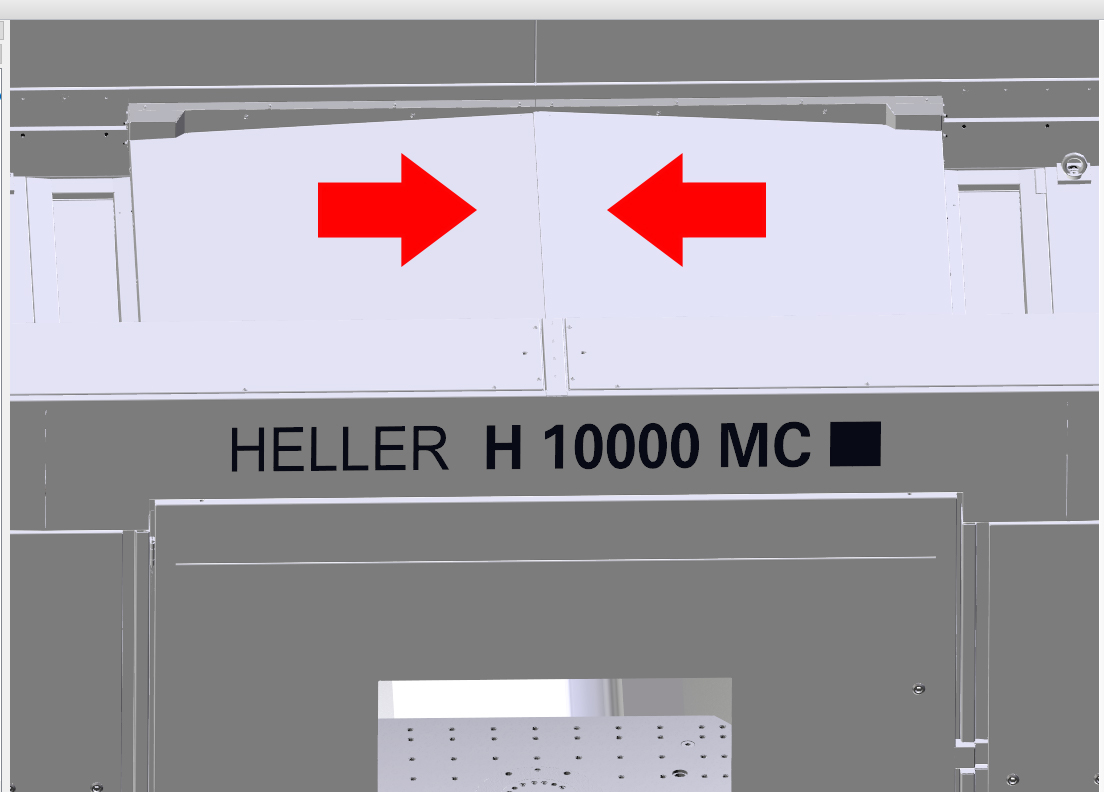
Loading hatch closed. Step 3: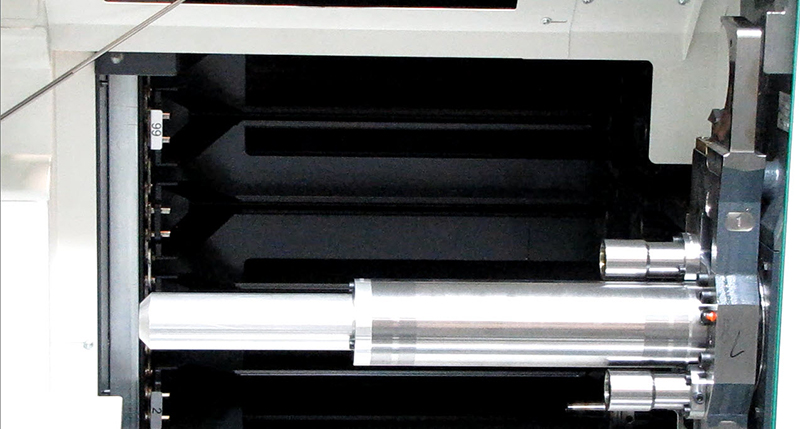
Move magazine place 1 (empty location without tool cartridge) to the conveying station towards tool changer. Because the control is unaware that the chains have elongated, magazine place 1 is no longer at the reference position. Step 4: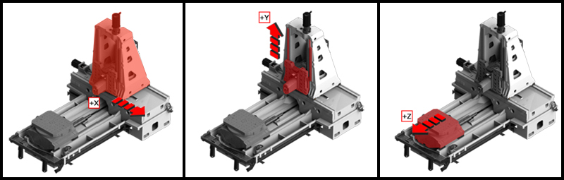
Position the linear axes such that the tool changer door is easily accessible:
Step 5:Grant access rights for "Individual functions" operating area. Step 6: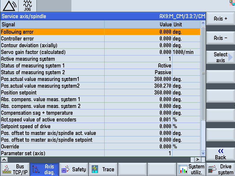
Check measuring system position display:
Step 7: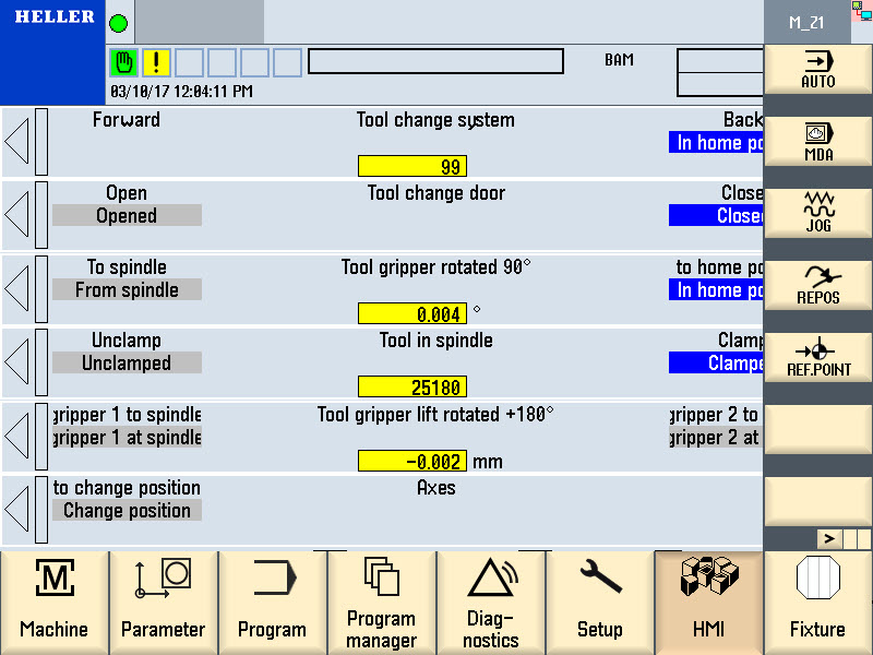
Select the "Tool change individual functions" main menu. Step 8: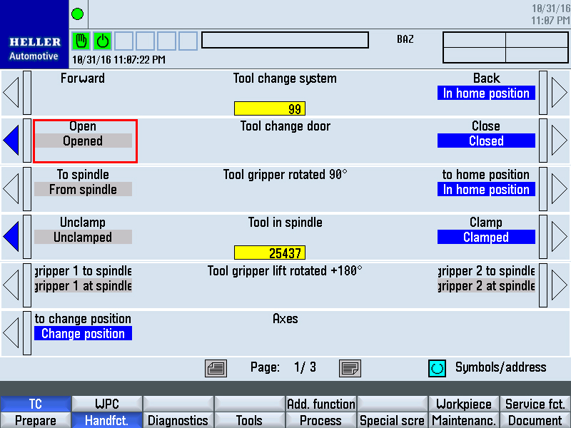
Open tool change door using the "tool change door" individual function. Step 9: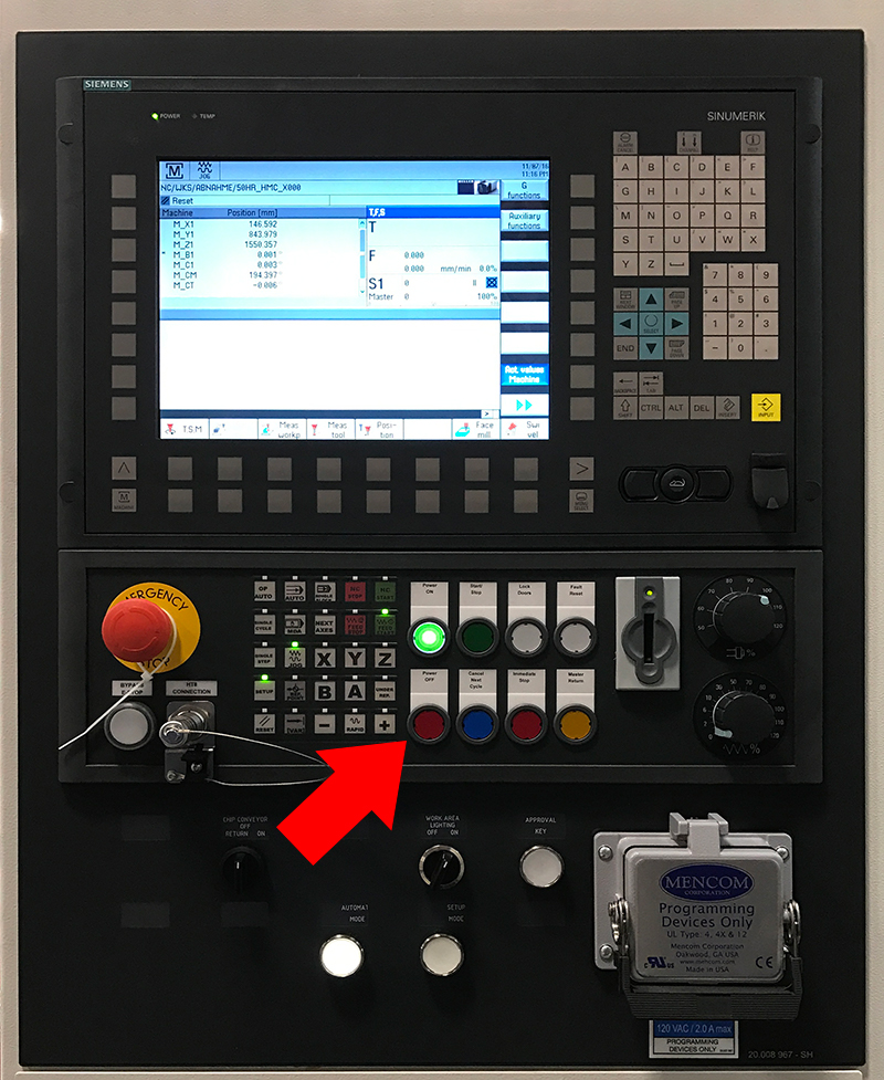
Switch off motors. Step 10:
Open work area safety door and secure to prevent closing. Step 11:
Switch off machine at main switch and secure against being switched on again. Step 12:
Secure tool change door to prevent it from falling. Step 13: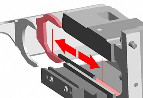
Determine deviation between target and actual position.
Step 14:Converting the deviation to angular degrees. Observe positive and negative values according to the following tables: 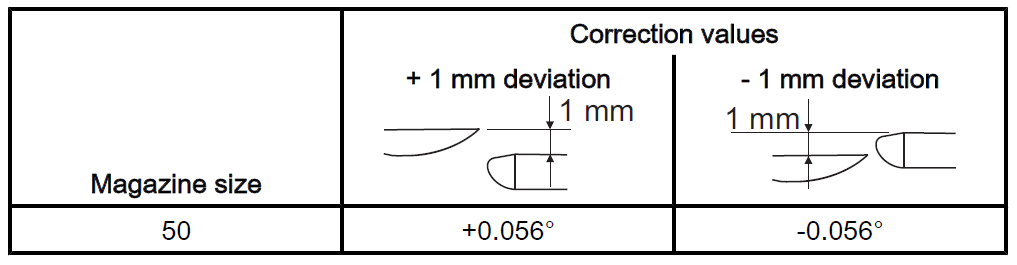
Step 15: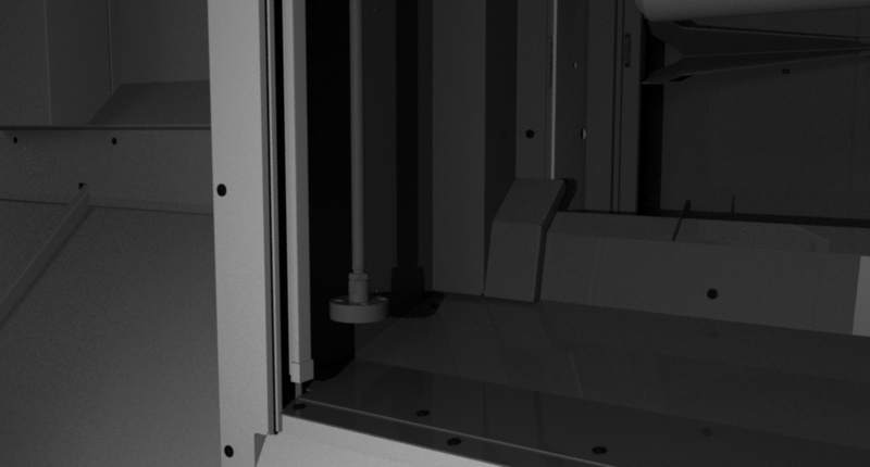
Remove support from the tool change door. Step 16:
Before closing the safety door, ensure that nobody is in the work area. Close work area safety door. Step 17: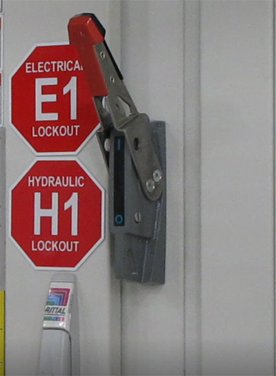
Turn on machine on at the main switch. Step 18:
Switch on motors. Step 19: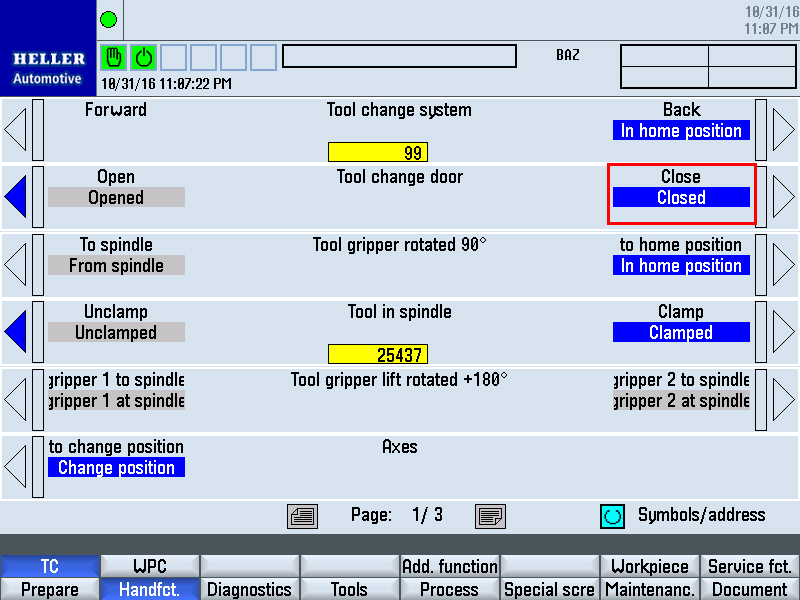
Close tool change door using the individual function. Step 20: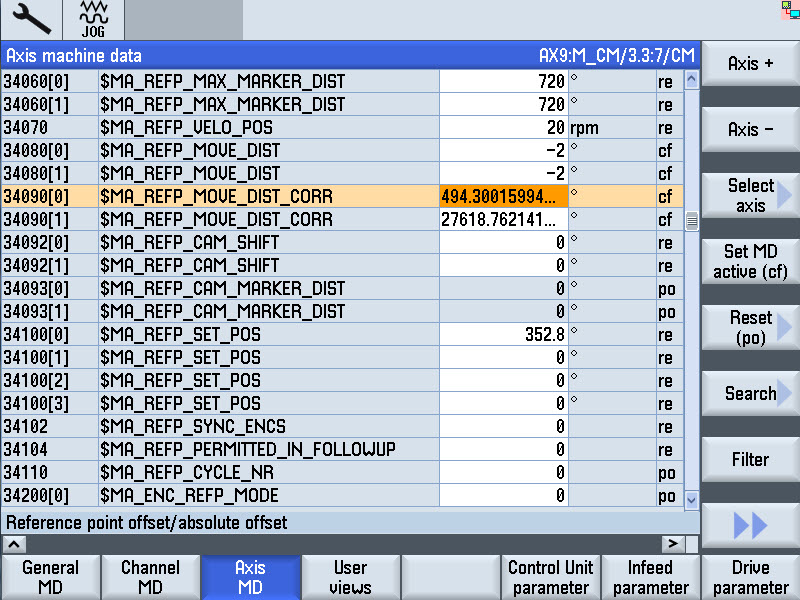
Select the "Commissioning" main menu.
Step 21:Grant access rights for "Commission" main menu. Step 22:
Enter adjustment value:
Step 23: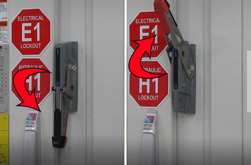
Turn the main switch off and on again. The actual position of the tool magazine is displayed in the actual value display of the main operator panel. Checking adjustment and re-adjust if necessaryProcedure Run the tool magazine through its complete cycle again in both directions. Check height of the conveying station. Readjust deviations. Proceed as previously with the first adjustment. Checking cartridge transport between conveying station and tool changer provisioning placeStep 1:
Step 2:
Machine switched on. Step 3:
Work area safety door is locked. Step 4:
Motors are switched on. Step 5:
Tool change door closed. Step 6:
Move a magazine place with tool cartridge to the conveying station towards the tool changer. Step 7:
Open tool change door with individual functions. Step 8:Use the "Tool traverse attachment" individual function to move the tool cartridge to and fro between conveying station and tool changer provisioning place. At the same time, observe the tool cartridge movement. The tool cartridge must move back and forth without jerking. Step 9:
Close tool change door with individual functions. Step 10:If the tool cartridge transport was not perfect, readjust the conveying station and repeat all checks. Step 11: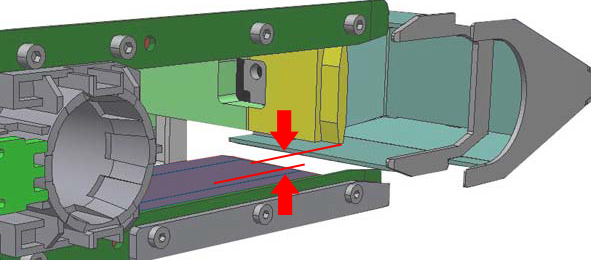
Because measuring system 2 sits flush over the tool setting station, tensioning has only a slight effect on this side. After repeated tensioning however, the deviation may exceed tolerance permitted here. The cartridge transport between conveying station and tool changer provisioning place is smooth. Step 12:Move magazine place 33 on the conveying station towards the tool changer. Magazine place 1 (empty location without tool cartridge) is located on the conveying station towards the tool setting station. Step 13:Issue access authorization for the "Commissioning" main menu. Step 14:Select the "Commissioning" main menu. Step 15: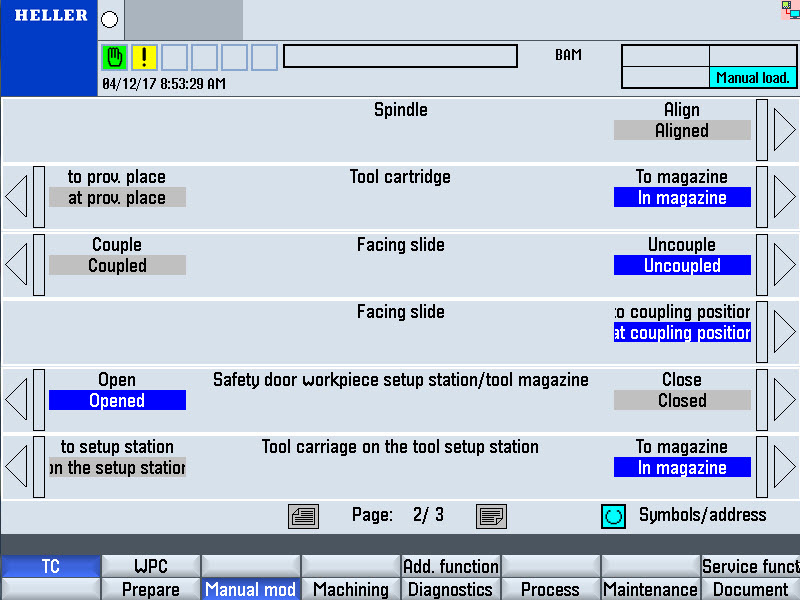
Open intermediate door:
Step 16:Synchronize chain-type magazine with the tool setting station via individual function "chain synchronization". The control switches over to measuring system 2. The chain-type magazine moves up by the offset between the two measuring systems. Step 17:
Unlock tool setting station safety door with intermediate door open:
Step 18:
Open maintenance door of the tool magazine. For more information on how to open the maintenance door see: "Opening the chain magazine maintenance door" Step 19:
Switch off machine at main switch and secure against being switched on again. Step 20:
Secure the intermediate door to prevent it from lowering. Step 21:
Determine deviation between target and actual position.
Step 22:Converting the deviation to angular degrees. Observe positive and negative values according to the following tables:
Step 23:
Remove support from intermediate door. Step 24:
Before closing the maintenance door, ensure that nobody is behind the guard panels. Close the maintenance door of the tool magazine. Step 25:
Close tool loading station safety door. Step 26:
Turn on machine on at the main switch. Step 27:
Switch on motors. Step 28:
Close intermediate door via individual function "Tool setting station/tool magazine safety door". Step 29:Issue access authorization for the "Commissioning" main menu.
Step 30:
Select the "Commissioning" main menu. Step 31:Enter adjustment value:
Step 32:
Turn the main switch off and on again. The actual position of the tool magazine is displayed in the actual value display of the main operator panel. Step 33:
Select the "Tool change individual functions" main menu. Step 34:Synchronize chain-type magazine with the tool setting station via individual function "chain synchronization". The control switches over to measuring system 1. The chain-type magazine moves up by the offset between the two measuring systems. Checking adjustment and re-adjust if necessaryProcedure Run the tool magazine through its complete cycle again in both directions. Check height of the conveying station. Readjust deviations. Proceed as previously with the first adjustment. Checking tool cartridge transport between magazine place and provisioning placeStep 1:
Step 2:
Maintenance door of the tool magazine closed Step 3:
Machine switched on. Step 4:
Tool loading station safety door locked. Step 5:
Work area safety door is locked. Step 6:
Motors are switched on. Step 7:
Intermediate door closed. Step 8: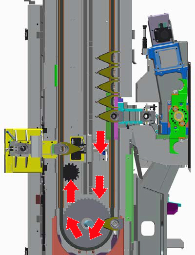
Move one magazine place with tool cartridge on the conveying station towards tool setting station. Step 9: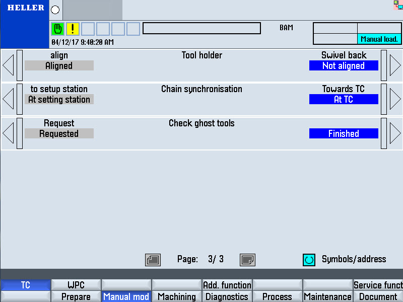
Individual function "Tool holder" to "Align". The chain synchronisation is switched over to the tool setting station. Step 10:Use the "Tool cartridge on tool setting station" individual function to move the tool cartridge to and fro between conveying station and tool loading position. At the same time, observe the tool cartridge movement. The tool cartridge must move back and forth without jerking. Step 11:
Individual function "Tool holder" to "swivel back". The chain synchronization is switched over to the tool changer. Step 12:If the tool cartridge transport was not perfect, readjust the conveying station and repeat all checks. Loading the tool magazineStep 1:Move magazine place 1 to the cartridge unloading position. Depending on the magazine size, the following magazine place is located at the tool setting station:
Step 2:
Unlock and open the tool loading station safety door Step 3:
Switch off machine at main switch and secure against being switched on again. Step 4:
Open maintenance door of the tool magazine. For more information on how to open the maintenance door see: "Opening the chain magazine maintenance door" Step 5: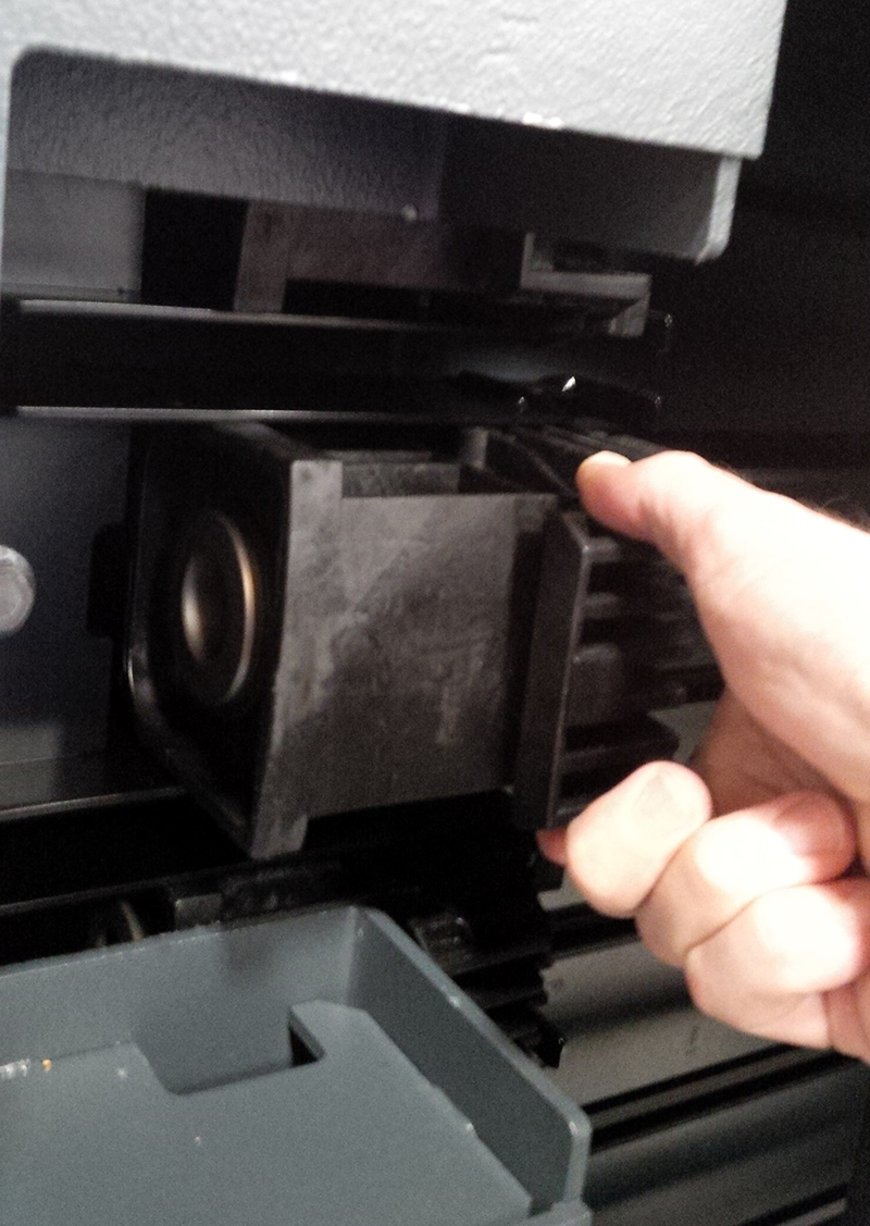
Reinsert the removed tool cartridge into tool holder 1. Step 6:
Fit the cover. Step 7:
Attach safety guard. Step 8:
Before closing the maintenance door, ensure that nobody is behind the guard panels. Close the maintenance door of the tool magazine. Step 9:
Close tool loading station safety door. Step 10:
Switch the machine on. Step 11:
Replace the tools from the tool magazine in the tool magazine. Check tool transport between conveying station and tool changer provisioning placeProcedure Replace the tools from the tool magazine in the tool magazine. CloseProcedure Revoke granted access rights. Save the new NCK data with "Series commissioning". Make two copies on separate data carriers. Place a tool in the tool spindle to protect the tool spindle from the ingress of dirt. Switch off motors. |
||||||||||||||||||||||||||||||||||||||||||||||||||||||||||||||||||