Replacing Hydraulic Hose LinesInterval 4 Years(s) Real time Component All hydraulic hose lines According to the Main Association of Industrial Associations of Germany, hydraulic hose lines must not be used for more than six years, including a maximum two-year storage period. Hydraulic hose lines are marked with the following information:
We recommend that all hose lines are replaced every four years. Combine the changing of the hose lines with the oil change. Proceed as follows:
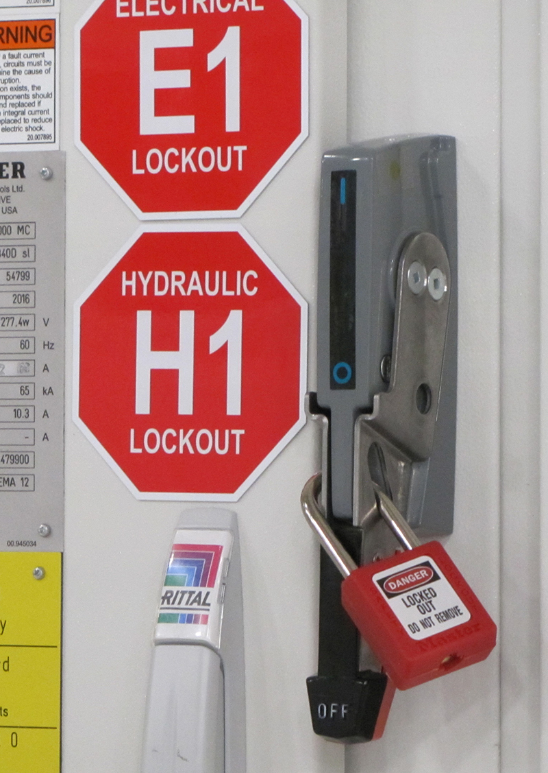
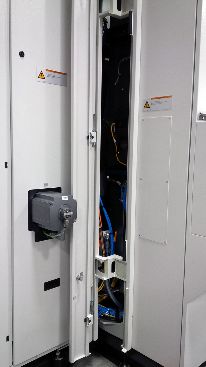
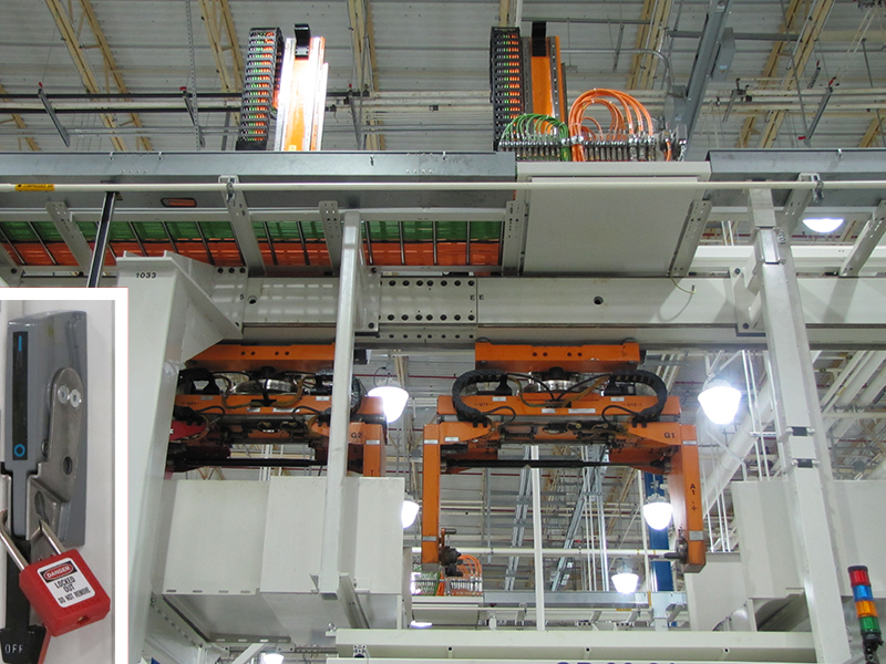
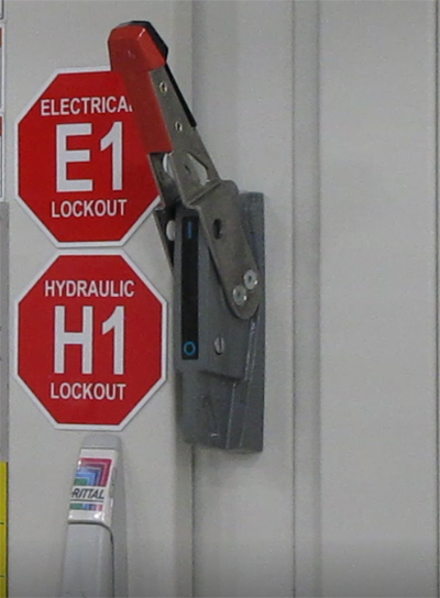
Consumable Hydraulic oil HLP 46 to DIN 51524, Part 2 (ISO-L-HM 46 to ISO 6743, Part 4) Purity class ISO 4406-18/16/13 Disimilar lubricants can contain various additives that might not be compatible. To rule out incompatibility between the lubricants, disimilar lubricants must not be mixed. If you have any questions, please contact your lubricant supplier. For hose lines with ordering data, see the media diagram (MP). Used oil and oily hose line should be regarded as hazardous waste. Dispose of these materials and components according to the locally applicable regulations. 15 litre container Making hose lines accessiblePlease observe chapter 4.2 "Special safety measures" when entering or leaving the machine. Danger to life within the traversing range of the gantry loader. Before climbing onto the machine, always move the portal loader to its parking position, switch off and secure to prevent it being switched on again. Do not remove gantry loader padlock before end of work or before removing the ladder. Step 1:Step 2:Step 3:Step 4:Step 5:Step 6:Step 7:Step 8:Step 9:Step 10:Step 11:Step 12:Replacing Hose linesWhen the hydraulic unit is switched off, various levels of pressure remain inside different sections of the line. Do not use the manual trigger of directional control valves to release residual pressure from the line. Do not readjust the directional control valves to ensure that upon restart, pressure is initially applied to the same side of the hydraulic cylinders as before. The cylinder will then be filled without piston movement. Otherwise, the piston will not be cushioned when travelling in the opposite direction against the end stop due to lacking counter-pressure. Lines containing residual pressure may be unscrewed carefully; pressure will be relieved quickly with the first drops escaping from the line. You must only continue to carefully drain the nominal volume of accumulator before completely releasing the hoses if the machine is fitted with an accumulator option. Use the media diagram to check whether this applies to your machine. Procedure Per hose line:
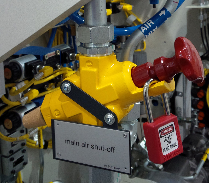
Open compressed air shut-off valve. Running in and venting the oil consumersAfter the hose line has been replaced, the system contains air. This will make hydraulic movements jerky. To vent the system, all parts must be moved back and forth several times without a workpiece or tool. As a result, the air is evacuated via the tank line. Step 1:Step 2:Step 3:Step 4:Before closing the safety doors and maintenance openings, ensure that nobody is behind the guard panels. Close the work area safety door and the maintenance area safety door. Close maintenance opening B. Step 5:Step 6:Step 7:Repeatedly enable all hydraulic movements with individual functions backwards and forwards. Checking for leaks and preparing machine for operationStep 1:Make hose lines accessible again:
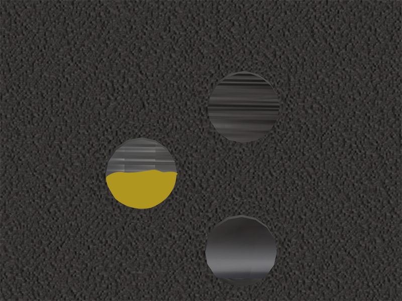
Step 2:Step 3:Check the oil level inside the hydraulic reservoir on the oil level indicator. Fill with oil up to maximum mark. Step 4:Step 5:Step 6:Before closing the safety doors and maintenance openings, ensure that nobody is behind the guard panels. Close the work area safety door and the maintenance area safety door. Close maintenance opening B. Step 7:Step 8:Step 9:Step 10: |
