Inspection of Fluid EquipmentInterval 1 Year(s) Real time Component All components of the cooling, hydraulic, central lubrication, pneumatic and cooling lubricant equipment These tests are best performed as part of the machine's basic cleaning routine, as all machine areas must be made accessible for both activities. This avoids doubling work. For the best sequence in which to proceed, see: "Cleaning the machine" For structure of the cooling unit, see the media diagram (MP). For structure of the hydraulic system, see media diagram (MP). For structure of the central lubrication system, see media diagram (MP). For structure of the pneumatic system, see media diagram (MP). For structure of the cooling lubricant system, see the media diagram (MP). Please observe chapter 4.2 "Special safety measures" when entering or leaving the machine. Danger to life within the traversing range of the gantry loader. Before climbing onto the machine, always move the portal loader to its parking position, switch of and secure to prevent it being switched on again. Do not remove gantry loader padlock before end of work or before removing the ladder. Proceed with caution if a tool is placed in the tool spindle whilst you are working within the work area. Step 1: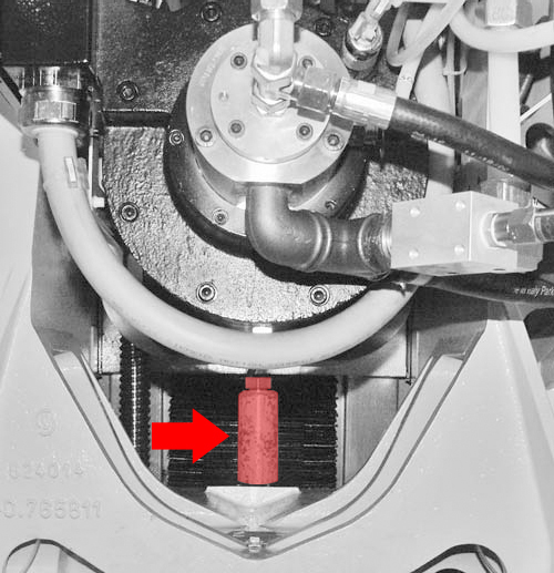
Machining unit traversed into support position. Step 2: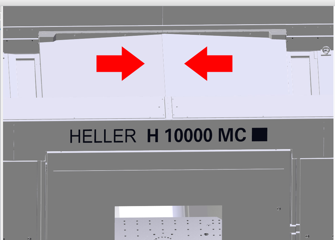
Loading hatch closed. Step 3: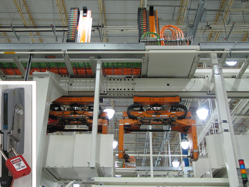
Gantry loader in parking position, switched off and secured against being switched on again. Step 4: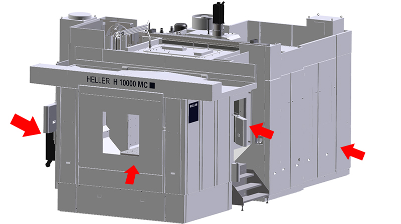
All safety doors open and secured to prevent closing. Step 5:Electrically protected doors, if available, open and secured to prevent closing. Step 6: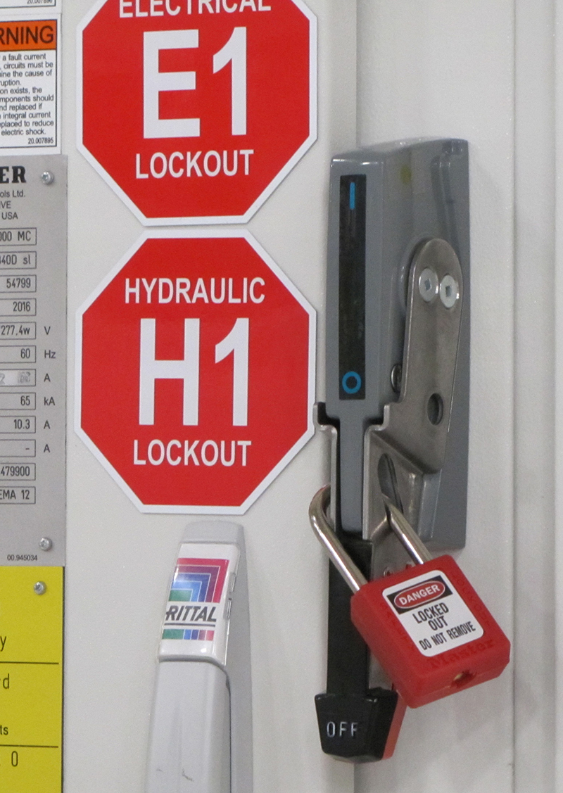
Machine switched off at main switch and secured against being switched on again. Step 7: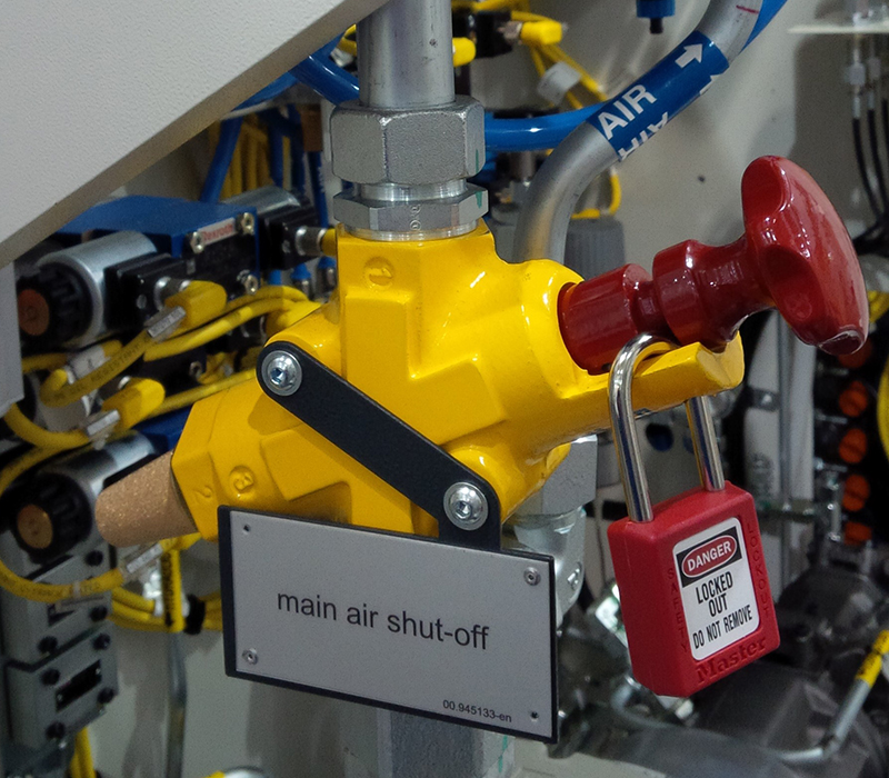
Compressed air shut-off valve opened. Step 8: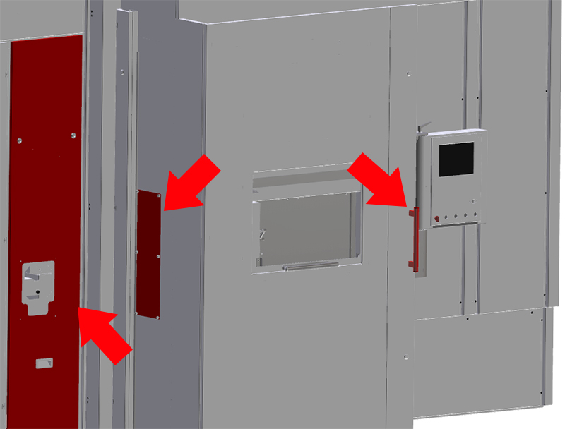
Maintenance openings open. Step 9:
Machining unit protected from falling by supports. Step 10: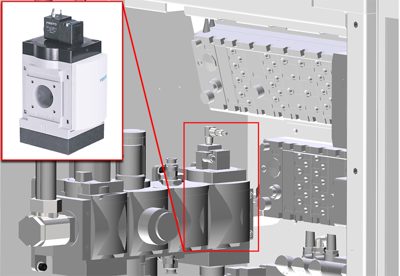
To check the pneumatic equipment, open the air supply on the startup valve (next to the maintenance unit): push in hand actuator using a screwdriver and turn to the right. Step 11: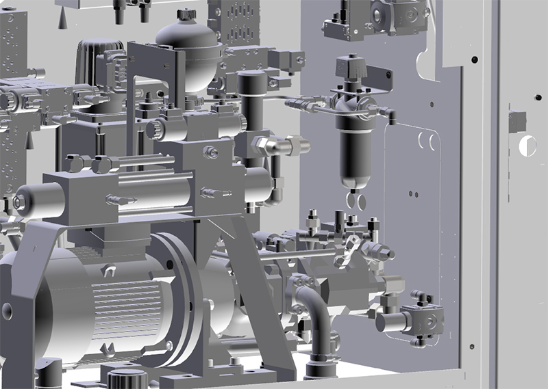
Check all fluid equipment components for leakages and visible external damage:
Step 12:Repair leakages and damage immediately. Do not operate machine with damaged equipment! Step 13:
Close air supply on the directional control valve: Remove screwdriver. Step 14:
Remove support from the machining unit. Step 15:Before closing the safety doors, maintenance doors and maintenance openings, ensure that nobody is behind the guard panels. Close safety doors, maintenance doors and maintenance openings. Step 16:
Remove gantry loader padlock. |