Tool Area SystematicsIntroductionFunction scope of the tool management systemThe tool management system supports you in all areas of tool
handling, e.g. the physical loading and unloading of the tool
magazine by data and tool transportation.
Tool List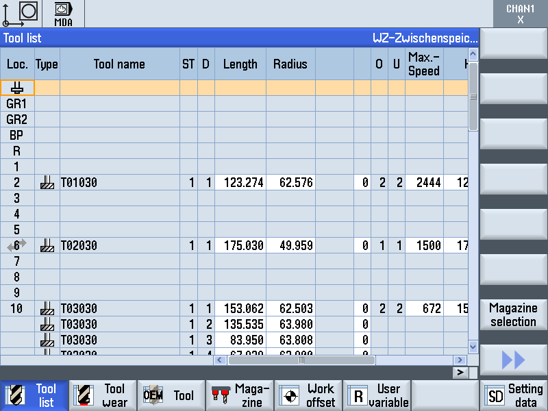
The tool list includes all tool data required for loading and unloading of tools. Necessary monitoring data also are managed here.
Tool wear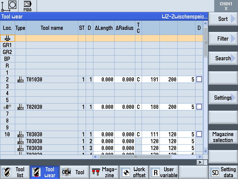
The "Tool wear" list includes all tool data that are important during machining. If the tool wear exceeds a certain value, an alarm is output. The following values are displayed:
Magazine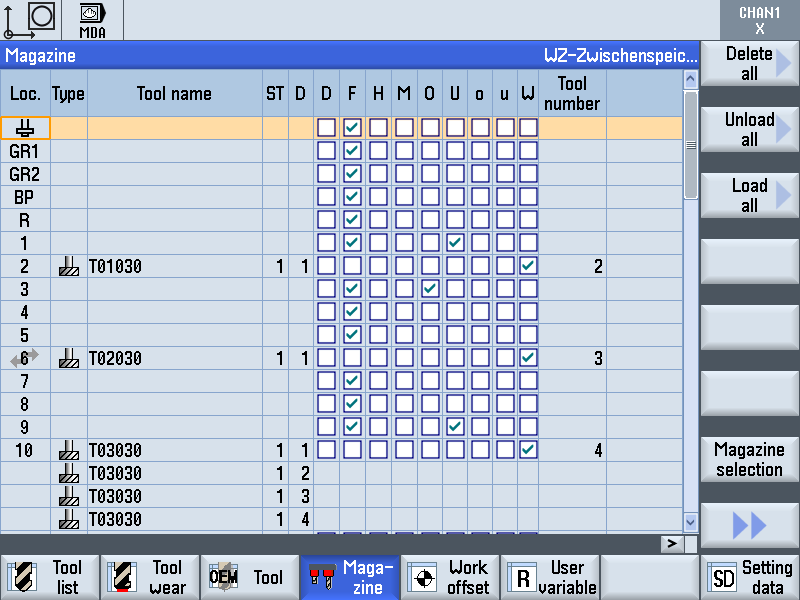
The tool and magazine are positioned using the "Magazine" list.
If a tool that is no longer required is unloaded from the magazine, the stored tool data can remain in the tool list for use at a later date. These tool data are shown at the end of the tool list. OEM tool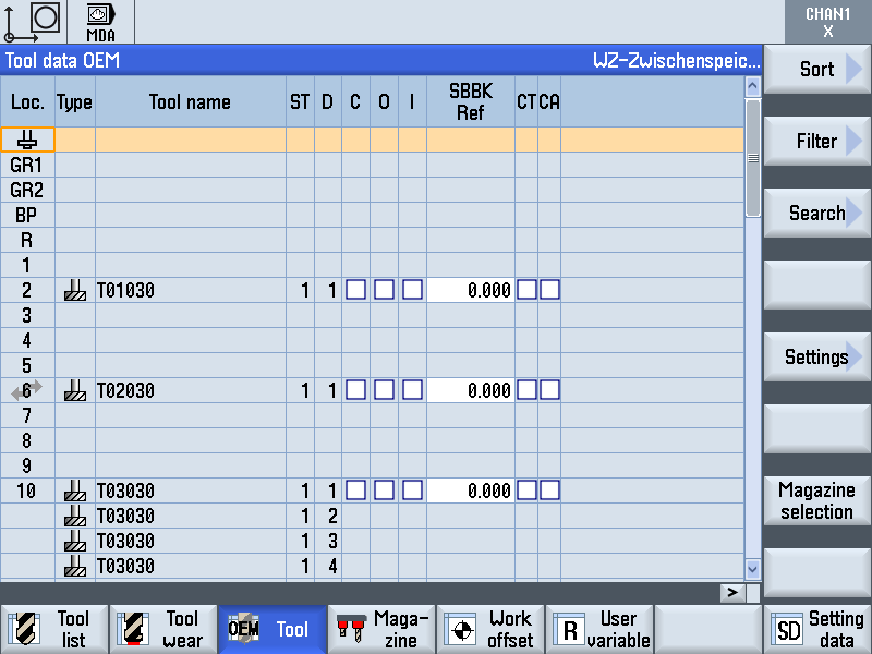
The "OEM tool" list includes data that are relevant for diagnostics
and troubleshooting.
More detailed information on the tool management system can be found in the SIEMENS documentation. Safe Tool HandlingCheck for correct balance of the tools. Unbalanced tools destroy the spindle bearing. The required balance quality of the tools is:
Make sure the tool geometry is within the permissible limits.
The control can guarantee collision monitoring only for tools with
known data. 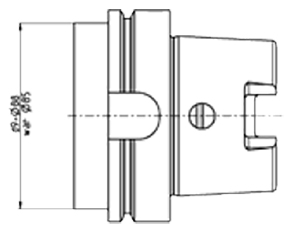
General handling dataAll user-related tool data for the magazine tools are managed in the
tool list.
Speed LimitingThe rotational speed at which the tools can be used is limited by
default. Where the tool data record of a particular tool contains no
speed value, a machine-specific maximum spindle speed defined by
HELLER automatically applies. Tool weight and tool change speed
Loading Tool in the Correct PositionWhen loading tools make sure that they are inserted in correct position into the tool cartridges at the tool setting station. -Hollow taper shanks tool holding fixture 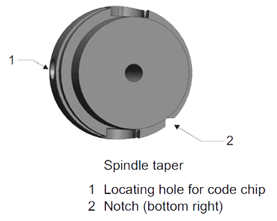
To insert a tool in correct position into the tool cartridge, the spindle taper must be positioned as follows:
Tool Loading StationFor manual loading of the magazine, a tool loading station is
provided on the side of the tool magazine facing away from the
machine. Following the loading operation during which a new tool is inserted,
the tool identity of the controller notified and the exterior safety door
re-closed again, the tool is automatically transported to the
magazine. A traverse attachment picks up the tool from the loading
place and slides in into the holder at the empty location provided in
the magazine. Settings Loading ToolsFurther function-oriented settings for tool loading are available to
persons with the corresponding access rights. Calling up the "Settings" windowStep 1:
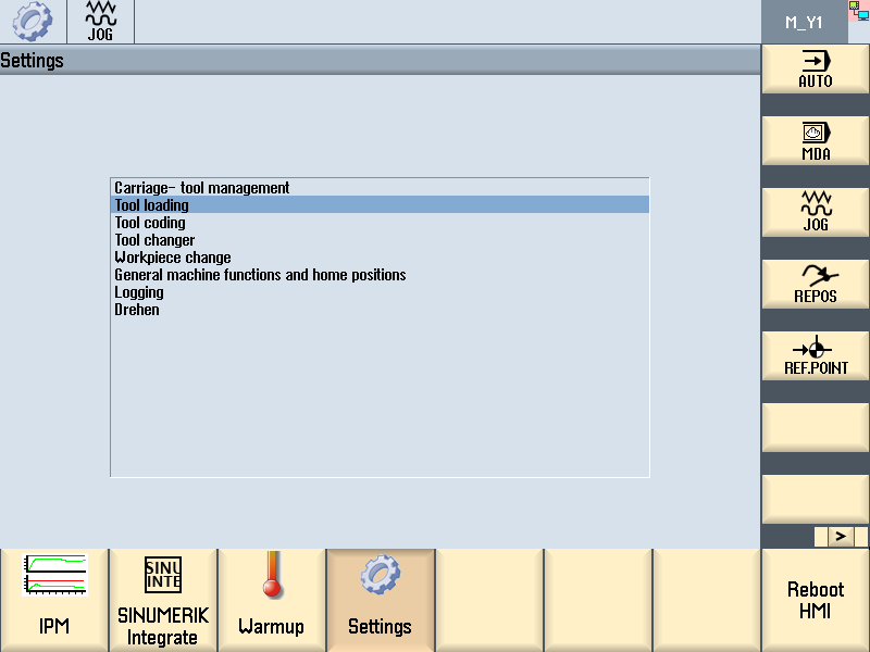
The corresponding access right is issued. Step 2: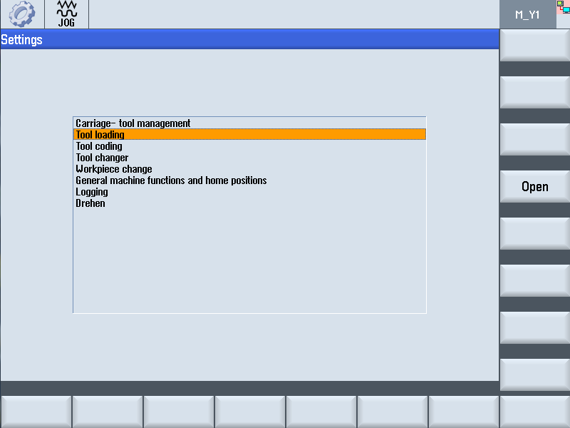
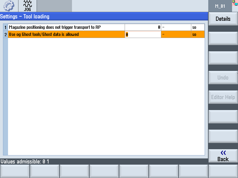
Highlight the "Tool loading" line using the Cursor keys. Step 3: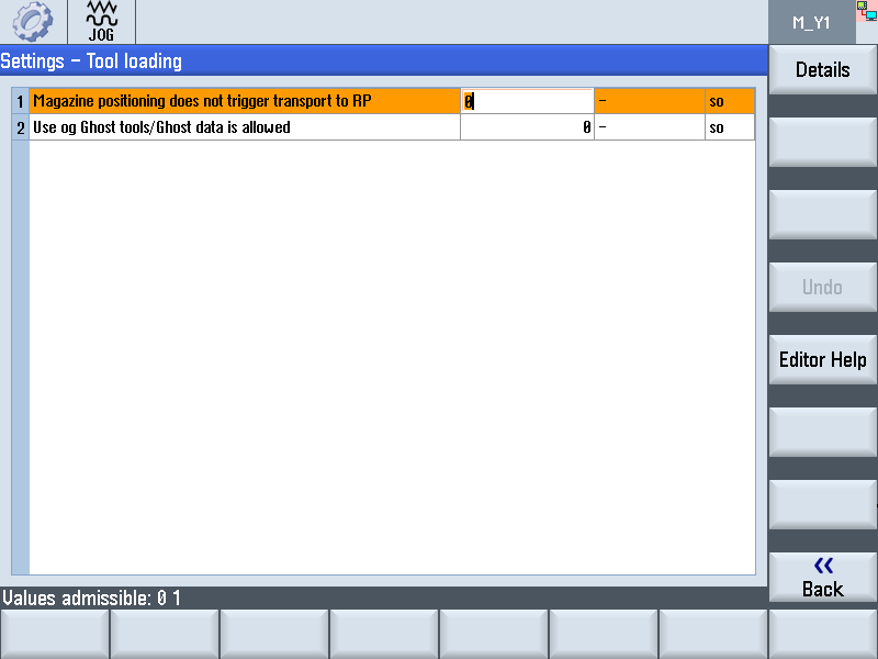
Select the settings you wish to change using the Cursor keys. Step 4: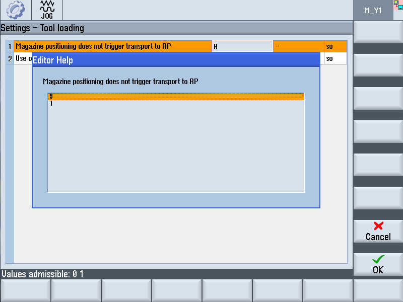
Select the desired parameter using the Cursor keys. Loading Tools With CodechipStep 1:Precondition:
Press the 'Parameter' softkey.
Press the 'Magazine' softkey.
Step 2:Select a suitable empty magazine place using the 'Cursor Keys'. Observe the plate at the tool setting station for half-place assignments of tools. Large tools occupy more than one magazine place. Press the "Position Magazine' softkey.
Step 3:Open tool loading station safety door. Step 4:
Hold tool in horizontal position and load firmly into cartridge. observe tool position. For further information see "Handling at the Tool Setting Station"Step 5: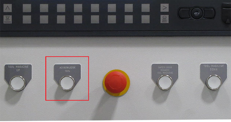
Observe 'Acknowledge Tool' key. The codechip read process is executed.
Step 6:Observe ACKNOWLEDGE TOOL key. The codechip read process is executed.
Remove tool from cartridge again. If necessary, press and hold ACKNOWLEDGE TOOL key for more
than 1.5 seconds. Step 7:Close tool loading station safety door. The setting operation is complete.
Unloading Tools With CodechipStep 1:Preconditions:
Press the "Parameter" softkey.
Press the "Tool list" softkey.
Step 2:Use the Cursor keys to select the tool you wish to unload.
Press the "Unload" softkey. The unloading operation is executed.
Step 3:Open tool loading station safety door. Step 4:
Observe ACKNOWLEDGE TOOL key. The data is written to the codechip.
Step 5:Take hold of the tool and at the same time push the pedal in front of the tool setting station with your foot.
When the pedal is pushed, and the tool is not released from the cartridge.
Step 6:Close tool loading station safety door. Press the SAFETY DOOR REQUEST TOOL MAGAZINE key to lock the safety door.
Loading tools without codehipStep 1:Preconditions:
Press the "Parameter" softkey. The "Tool" area is opened. Press the "Tool list" softkey. The tool list is displayed. Step 2:Use the Cursor keys to select the tool you wish to load.
Tools not located in the magazine appear at the end of the list
without a magazine place number.
Step 3:The next possible, empty magazine place is suggested. If necessary, enter a different magazine place using the Alphanumeric keys. Press the "Ok" softkey.
Step 4:Open tool loading station safety door. Step 5:
Hold tool in a horizontal position and load firmly into the cartridge. Observe tool position. For further information see "Handling at the Tool Setting Station" The tool is written to the buffer storage place "R" in the tool list and disappears at the end of the list. Step 6:Close tool loading station safety door. Press the SAFETY DOOR REQUEST TOOL MAGAZINE key to lock the safety door.
Unloading tools without codechipStep 1:Preconditions:
Press the "Parameter" softkey.
Press the "Tool list" softkey.
Step 2:Use the Cursor keys to select the tool you wish to unload.
Press the "Unload" softkey. The unloading operation is executed.
Step 3:Open tool loading station safety door. Step 4:Take hold of the tool and at the same time push the pedal in front of the tool setting station with your foot.
When the pedal is pushed, and the tool is not released from the cartridge.
Step 5:Close tool loading station safety door. Press the SAFETY DOOR REQUEST TOOL MAGAZINE key to lock the safety door.
Unloading tool and loading a different toolOnce you have unloaded a tool, you can immediately load another tool type to the cartridge at the tool setting station.
Step 1:Preconditions:
Use the Cursor keys to select the tool in the magazine you wish to load.Tools not located in the magazine appear at the start of the list with a magazine place number. Press the "Load" softkey. The magazine place already located at the setting station is displayed. Step 2:
Insert tool into the correct position. Performing visual inspection of tool without codechipTo determine the status of a tool, you can make a visual check at the tool setting station by removing and examining the tool. Depending on the outcome of the examination, you can reload the same tool or replace it by an identical, new tool. Step 1:Preconditions:
Press the "Parameter" softkey.
Press the "Tool list" softkey.
Step 2:Use the Cursor keys to select the tool in the magazine you wish to examine. Tools not located in the magazine appear at the start of the list with a magazine place number. Press the "Unload" softkey. The unloading operation is executed.
Step 3:Open tool loading station safety door. Step 4:
Remove the tool. Step 5:Continue to use used tool. No tool change required... Hold the same tool in a horizontal position and load firmly into the
cartridge.
The data for the tool are not changed in the tool list. Step 6:Close tool loading station safety door. Press the SAFETY DOOR REQUEST TOOL MAGAZINE key to lock the safety door. The visual inspection is completed.
Step 7Insert new tool. Tool change required... Hold the same, new tool in a horizontal position and load firmly into the cartridge. The data for the tool are not changed in the tool list. "Acknowledge tool" key lamp flashes. Step 8
Close tool loading station safety door. In the "Tool wear" list the following parameter values are changed:
Step 9Press the SAFETY DOOR REQUEST TOOL MAGAZINE key to lock the safety door. The visual inspection is completed.
Loading tool with code chip without write/read operationIn special cases, if the codechip is absent or faulty for example, tools can to be loaded without the write/read process. Deactivating the reading/updating code carrier functionIf the code carrier is not to be read or updated during tool loading, you have to activate corresponding functions. To do so, there are general functions available in the "Settings" menu. In addition, it is possible to deactivate the reading process for individual tools in the tool list. Step 1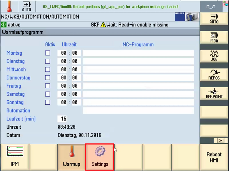
The setting made in the "Tool coding" menu generally apply to all tools within the machine. These settings remain in force even after a machine restart and must be reset. Press Data menu key. Press the etc. key. The "Settings" softkey is displayed. Press the "Settings" softkey. The "Settings" window will be displayed. Step 2: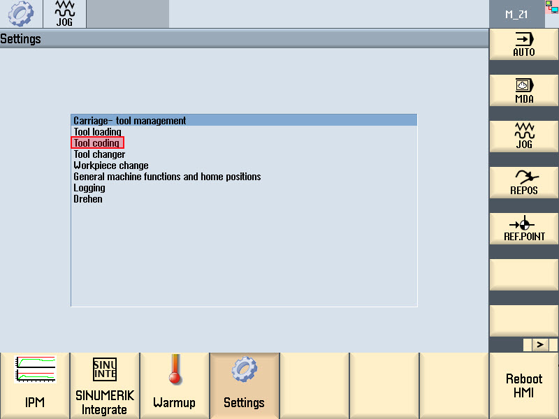
Select the "tool coding" line using the Cursor keys. Press the "open" softkey. The "Settings - tool coding" window is opened. Step 3: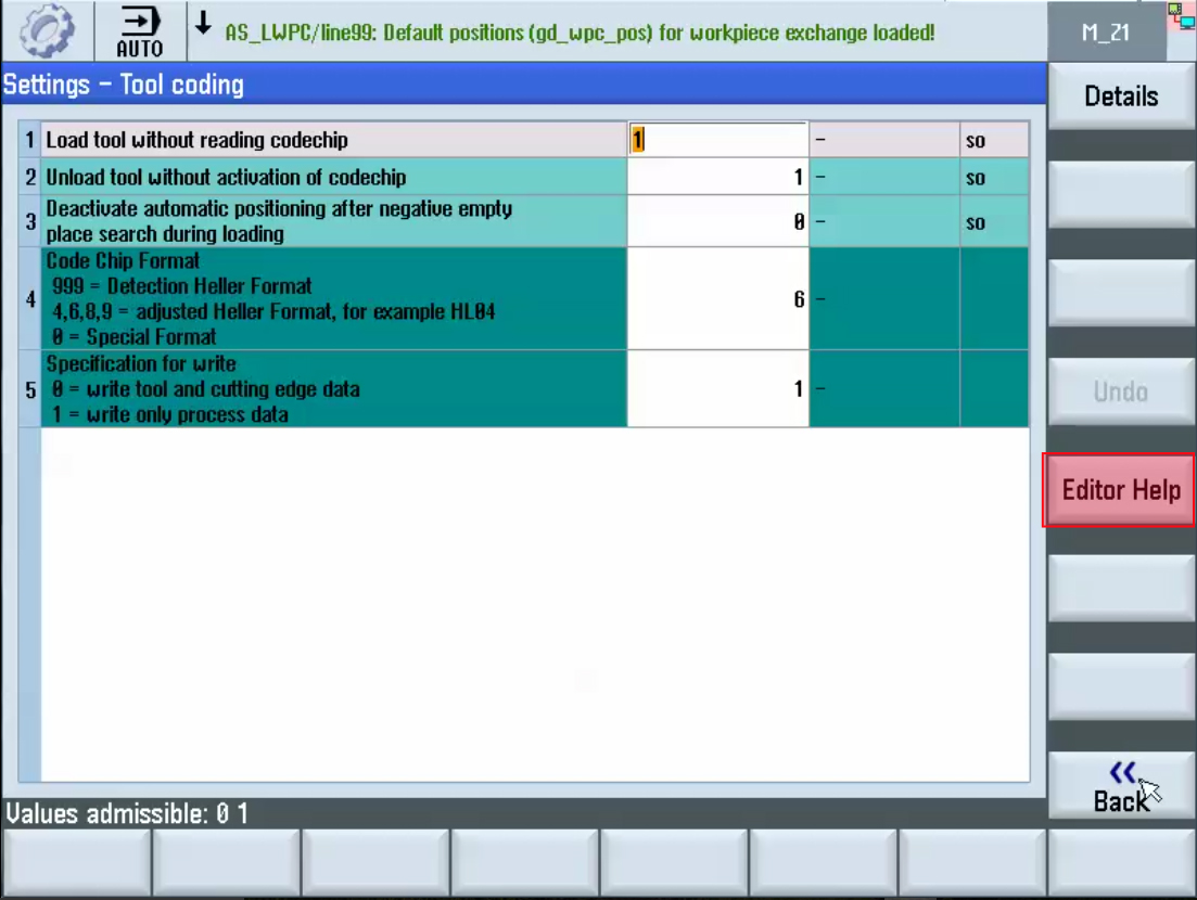
Select the required function using the Cursor keys. Press the "Editor Help" softkey. The "Editor help" window is opened. Step 4: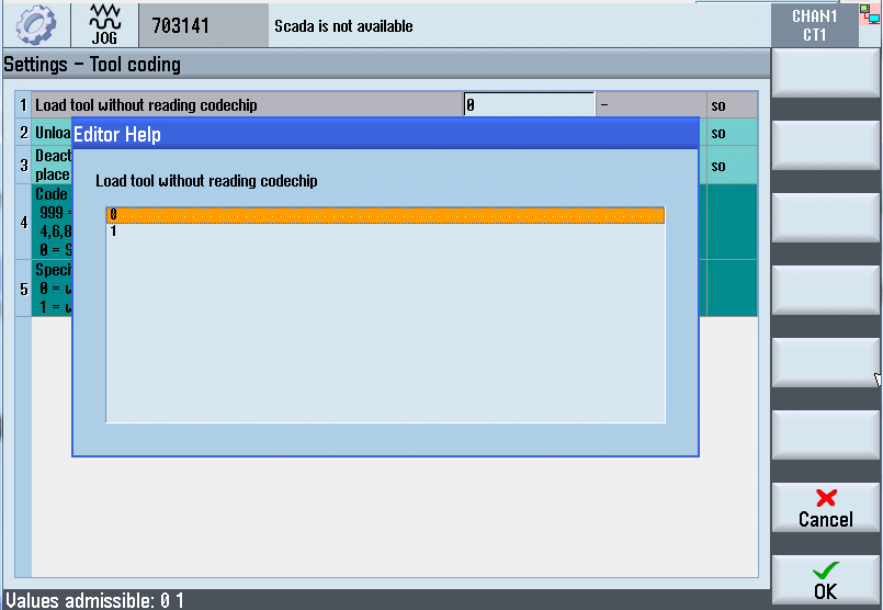
Use the Cursor keys to select parameter "1" in order to activate the function or select parameter "0" to deactivate the function. Press "Ok" softkey to accept the entry. Step 5: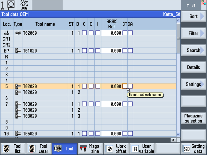
If a certain tool is to be excluded from the read process during loading, parameter "CT" must be activated in the OEM data tool list. The reading process is executed for all other tools. Press the "Parameter" softkey.The "Tool" area is opened. Loading ghost toolsDepending on the expansion stage of the machine, it may be useful to simplify the loading operation by loading "ghost tools". This especially accelerates the loading process significantly. "Loading of ghost tools" simplifies the loading operation when the following preconditions have been fulfilled:
To use the "Loading of ghost tools" function, you need to activate it. See also: "Settings - loading tools" 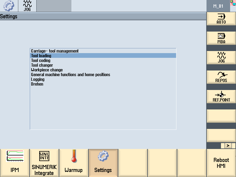
Preconditions:
Further information on "magazine" list, see Chapter "Magazine list" Step 1Preconditions:
Use the Cursor keys to select the tool you wish to load by data.
Press the "Load" softkey. Step 2: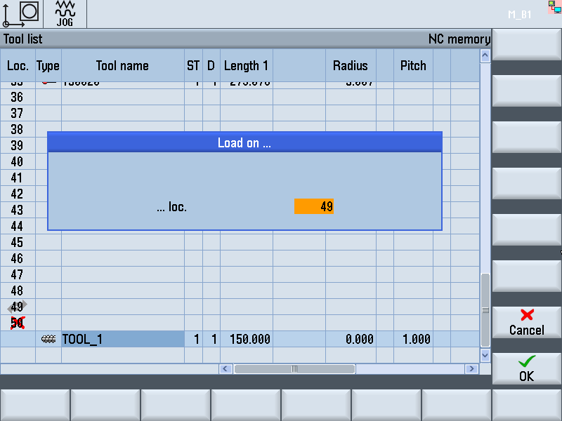
A magazine place is suggested. Make a note of the magazine place to which the tool was loaded by
data.
Step 3:Preconditions:
Press the TOOL MAGAZINE DOWN key on the standard operating unit of the tool setting station until a magazine place that is only loaded by data is at the setting station. -To do this, refer to your notes. Step 4:
Observe section. Step 5:Open safety door. Step 6: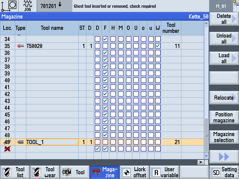
Insert the tool corresponding to the data. The following error text is displayed: "Ghost tool inserted or removed,check required" If you wish to insert a tool on a place that is already occupied, the
error message "Magazine place already occupied" is displayed. Step 7:Close and lock the safety door. Step 8:
After inserting ghost tools, it must be ensured that the corresponding data is available for each tool in the magazine or a tool has been inserted for all the tool data. The "Check ghost tools" function is provided for this purpose. At the next tool provisioning all magazine data are compared to the "Tool present" bit. In case of a deviation, a corresponding error message is output. Press the Setup key.
The machine is removed from the system linkage.
Setup mode is activated. Step 9: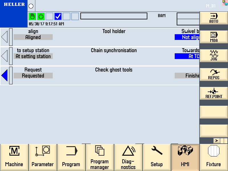
Press upper horizontal softkey "HMI". Then press "Manual Mode" and "TC". Step 10:
Scroll to page 3 in the "Tool change" menu and trigger the "Check
ghost tools - request" function.
Step 11:Rectify errors in the magazine if needed and again execute the "Check ghost tools" function. For further information on executing individual functions, refer to "Initiating individual functions" Fundamental PrinciplesThe lists in the tool area show all tools and, if configured, also all
magazine places, which have been created and/or configured in the
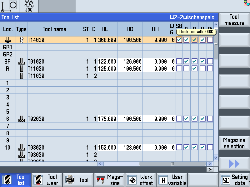
NC. Tool ListAll parameters and functions for creating and setting tools are displayed. Tool WearLocated here are all parameters and functions that are required during operation, e.g. wearing and monitoring functions. OEM Tool DataThis list is available to the OEM for free design. MagazineLocated here are the magazine-related and/or magazine placerelated parameters and functions for the tools/magazine places. Context sensitive helpIrrespective of which tool you select in the list, the corresponding data for this line will be displayed. This means, for example, that a column for the point angle is available for a drill or a second radius can be entered for a milling cutter. The meaning of the individual columns will be displayed when you select the field concerned. Geometric dataIf a further tool is to be included in or deleted from the lists, you must do this in the tool list. A tool created in the tool list will automatically appear in all further lists. The tool list contains all geometry data. Tool wear data can be found in the "Tool wear" list. For a description of the individual lists, see next Chapter. Further geometric data can be displayed in the lists using the scrollbar at the bottom of the screen. Unit of geometric data is mm, resolution 0.001 mm (= 1 µm) Edit geometric dataMost data can be edited in the lists themselves. To do this, use the "Cursor" keys to select the required value and enter the new value with the "Alphanumeric" keys . The new value will be accepted as soon as you exit the selected fields with the "Cursor" keys. Tool ListAll relevant geometry and handling data of tools are managed in the tool list. Handling data such as envelope contour or speed of changing are needed by the system module to enable size-related position assignment and to carry out tool transport without collisions. Step 1Press Data menu key to call-up the machine's basic menu. Press the "Tool list" softkey. Step 2:Actual display may differ. Step 3: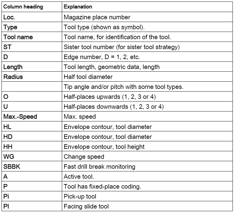
List of parameters Step 4:The softkey "Magazine selection" is used to navigate between the NC memory, tool buffer and the chain. Creating New tool in the tool listStep 1:The "tool list" window is open. Step 2: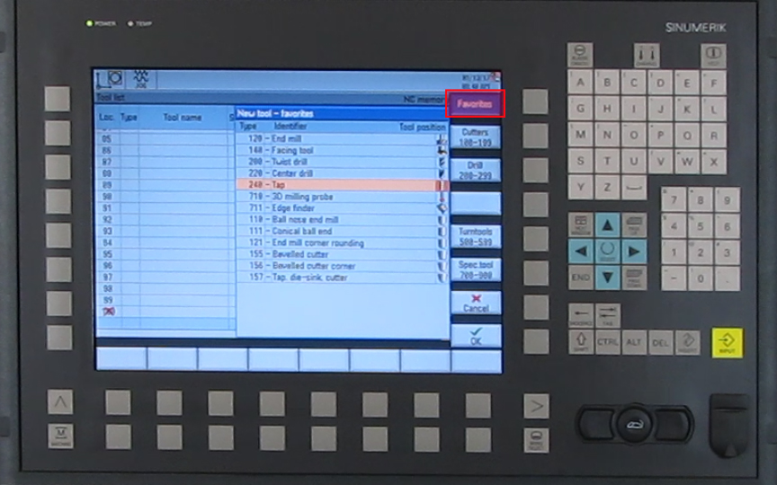
Press the right softkey "Favorites". Step 3:Select the required tool type from the right menu bar. geometric dataDefining Place CodingColumn P in the tool list can be used to specify either variable or fixed place coding for each tool. 
It is generally required to mark the column "P" for "Tool at fixed
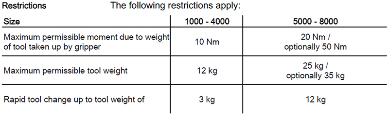
location". Specify Changing SpeedThe tools must not exceed the specified weights and moments of weight. The tool changer may run with heavy tools only at reduced change speed. 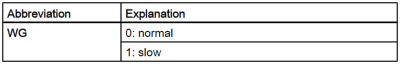
See also General layout and Technical data. The documents always appear in the chapter headed "Drawings, Plans" in the Machine Operator Manual (BD). Maximum Speed
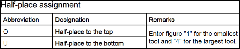
See Chapter Specify envelope contourTools may occupy more than one magazine place. In order to define the place assignment for a tool within the magazine, you have to determine the half-place assignment for the tool by means of the tool's envelope contour. Envelope contour and parameters for the half-place assignment must be entered into the tool list.
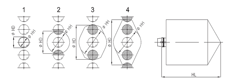
4 Possible situations for the half-place assignment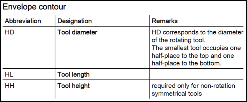
Tool wear ListCutting tip-related monitoring data are managed in the "Tool wear
list". Step 1:Preconditions:
Press the "Tool wear" softkey. Step 2: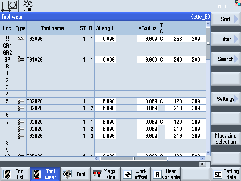
Actual display may differ. Step 3: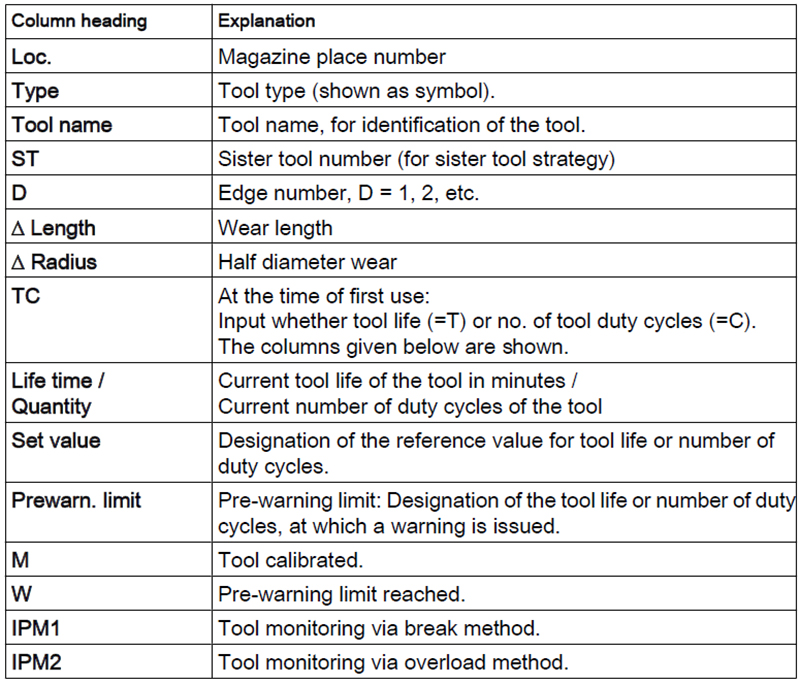
The tool wear data can also be called-up directly in the "HMI" main menu ("Tools - Wear" menu). Step 4: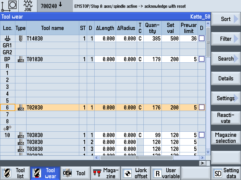
You can use the "Reactivate" softkey to reset individual edge wear values to the setpoint. Select the required tip using the Cursor keys and press the "Reactivate" softkey. If the tool is disabled due to the wear values for this tip, it will now be released. In the case of machines with a tool magazine, the softkey is of less importance, since the corresponding wear values are reset automatically (to the reference value for tool life/number of duty cycles), when new tools are loaded. OEM Data Tool ListThe user-related tool data for the tools are managed in the "OEM
tools" list. Step 1:Preconditions:
Press the "OEM tools" softkey. Step 2: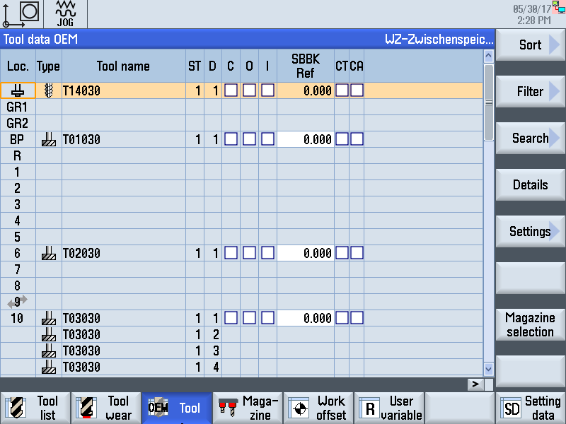
Actual display may differ Step 3:
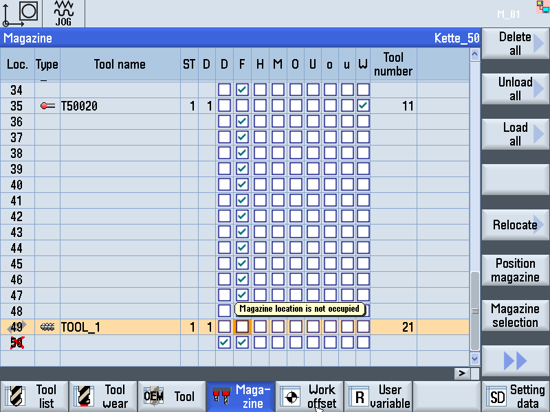
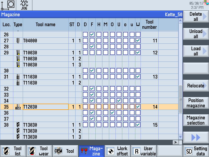
List of Parameters. Calling up the Magazine ListStep 1:Preconditions:
Press the "Magazine" softkey. Step 2: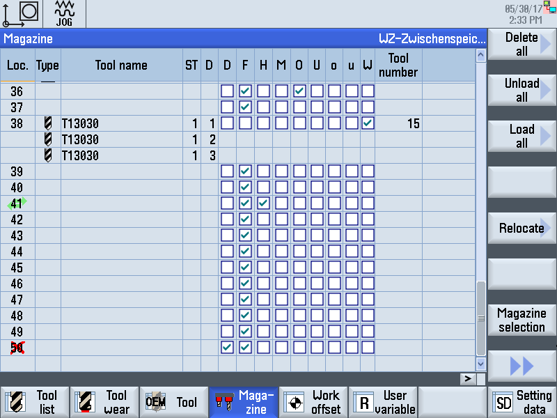
Actual display may differ. To avoid errors, the last magazine place must always be disabled. This means that parameters "G" (disabled) and "F" (magazine place not occupied) must be selected. Step 3: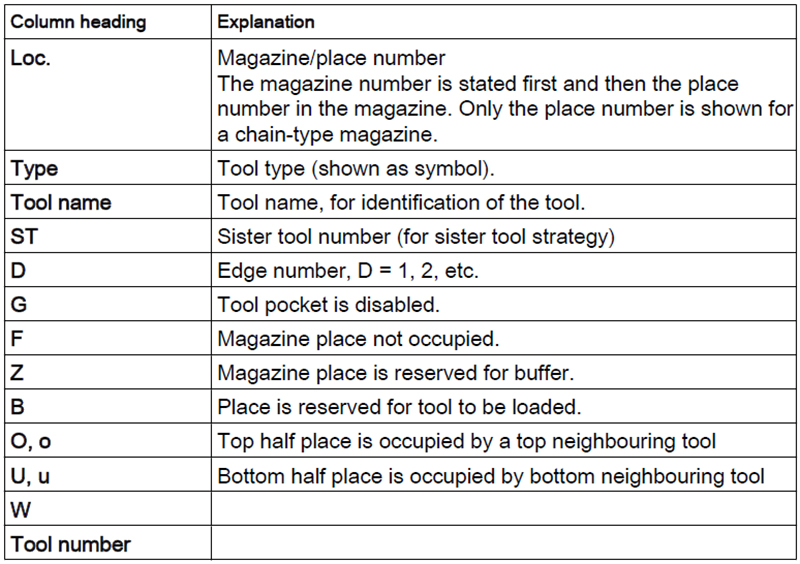
Large tools occupy more than one magazine place. The "Magazine"
list reflects for example parameters for the envelope contour and the
half-place assignment entered in the tool list. Step 4: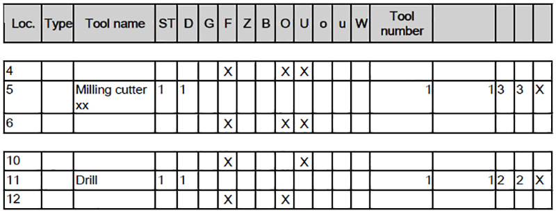
Tool is located in the magazine As an example, the display is explained by means of the tools on place 5 and place 11: Milling cutter on place 5 Drill on place 11
The drill takes up 2 places. Step 5: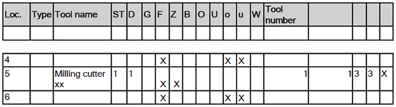
The tool is located inside the spindle or at the provisioning place When the tool is placed inside the spindle or moved to the provisioning place, the place in the magazine must be kept free. Halfplaces must be taken into consideration: The tool on place 5 has been placed into the spindle. The place is
kept empty for intermediate storage. Step 1: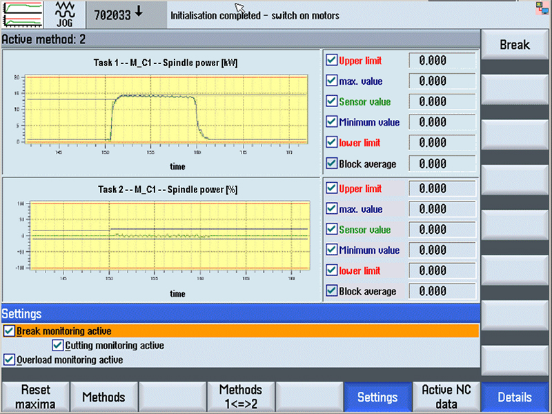
Integrated Process Monitoring (IPM) is a dynamic addition to the
existing standard procedure in connection with tool management. Fast Drill Break MonitoringGeneralIf a tool is to be measured using "Fast tool break monitoring", the
parameter for the "fast tool break monitoring" must be entered into
the tool list after the tool has been loaded into the magazine. This
activates "Fast tool break monitoring" for this tool. 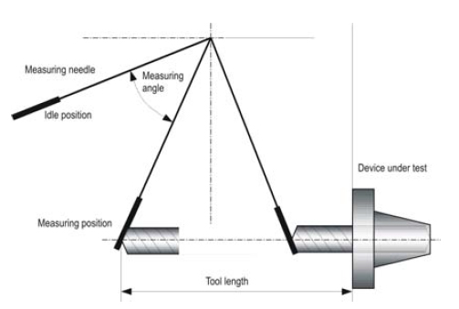
To prevent a waiting period occurring during measuring, the traverse
movement can be triggered at the next machining position as early
as the tool change. ApplicationThe "Fast tool break monitoring" option supplements the online monitoring facility "Integrated Process Monitoring (IPM)" This enables the checking of tools, which due to their low performance/ torque and/or feed power can no longer be reliably recorded by the "IPM".Fast tool break monitoring is intended particularly for time-critical NC machining, which involves predominantly those tools listed below. The following tool types can be monitoring particularly effectively with the "Fast tool break monitoring" option. - Drilling tools diameter up to 5 mm, e.g. - HSS drills - Coated drills - Solid carbide drills - Step drills - Tap up to M6 Tool fracture monitoring on tools with a diameter greater than 5 mm may only be included in the monitoring option following consultation with HELLER. Fast tool break monitoring can of course be combined with the alternative strategy (option), which reacts appropriately to a tool break without parts machining coming to a halt. |

 Before the first tool is loaded, a reference measurement is taken at
the provisioning place. The determined value is entered into the
"OEM tools" list against the "SBBK" parameter.
Before the first tool is loaded, a reference measurement is taken at
the provisioning place. The determined value is entered into the
"OEM tools" list against the "SBBK" parameter.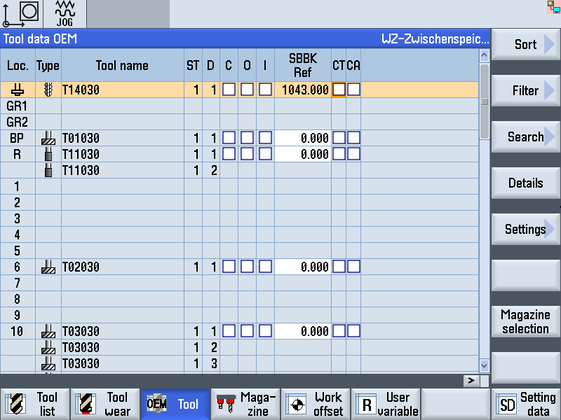 The "Fast tool break monitoring" option allows tools to be checked
for breakage during a tool change. Only complete broken tools are
detected, not breaks in individual cutting tips. Length changes of 2
mm and more (tolerance), which may result in a tool break, are
detected.
The "Fast tool break monitoring" option allows tools to be checked
for breakage during a tool change. Only complete broken tools are
detected, not breaks in individual cutting tips. Length changes of 2
mm and more (tolerance), which may result in a tool break, are
detected.