General FunctionsAccess Level ConceptThe unit controls use an access level concept for access to data areas and the special operating mode (setup). Access levels 1, 4, 6 and 7 have been declared for the access level concept on this system. Electronic KeyThese access levels are enabled by the Electronic Key System (EKS) in the machine control panel and the corresponding electronic keys. The colour-coded keys contain the access codes for the entitled group of persons concerned. When the machine is installed locally, the owner can have access to the special operating mode (setup) managed, e.g. by assignment to access levels 1, 4 and 6. These three access levels require a EKS key, whereas access level 7 does not. In the case of the latter, only normal operating mode (automatic) would be selectable. 
Electronic Key SystemThe Electronic Key System comprises two components:
The data carrier in the electronic key is fitted with a combined write/ read and fixed code memory area:
The key holder is a write/read system with integrated evaluation electronics and interface. For operation, the electronic key is inserted into the key holder and held in place by a spring clamp. The power for the transponder and the data is transmitted without physical contact between the key holder and the electronic key. Electronic Key ManagerThe key is managed for various access levels by the "Electronic Key Manager (EKM)" software at a separate PC workstation. Disabled Collision MonitoringMain menus with switch on/switch off collision monitoring, e.g. individual functions, are exposed to a higher risk. Particular care and a rigid procedure are required when working with these functions. Therefore, the machine display and selection windows have been removed from the general protection stage concept (see "Operating in special situations" Chapter). 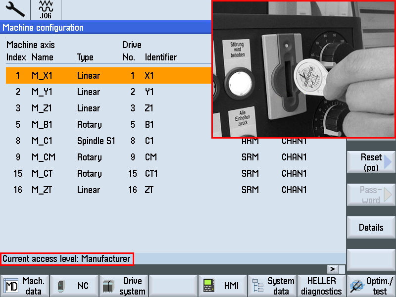
When the machine is being installed on-site, the operator can arrange to have a special protection stage set up for this sensitive function, which only allows collision monitoring to be switched off under certain conditions. If you have to switch off collision monitoring for your particular task, let your supervisor know so that access to the function can be authorised. Ensure that on completion of the task, the access right to the machine is reset to its basic status. Step 1: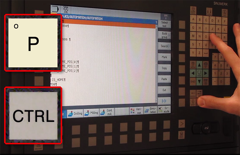
To make a screenshot, go to the screen you want to copy. Then on the operator panel, press the control (CTRL) button and the letter "P" at the same time. When you do this, a camera will appear momentarily on the screen to let you know it has been copied. Make sure the password is set in the control before continuing Step 2: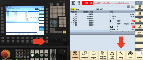
After the screenshot is made, to retrieve the screen shot press the Menu Select button and select Setup. Step 3: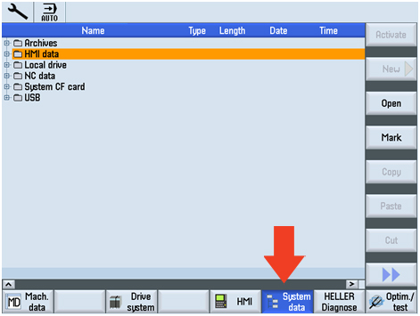
Once in the Setup screen, select System data. This will show a list of all the folders. Move the cursor down to HMI data and press the yellow input button. Once the folder opens, move the cursor down to Logs and press the yellow input button Step 4:
When the Logs folder opens, you will see the folder Screenshots. All your screenshots will be in this folder. You can use the copy function and copy them to the USB folder (have a USB stick installed). Step 1:Preconditions
Step 2: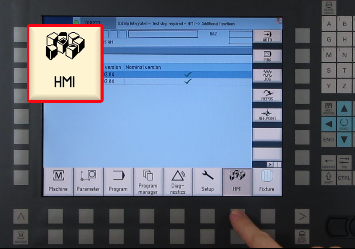
Press the "HMI" associated softkey at the HMI Panel... the Prepare screen appears. Step 3: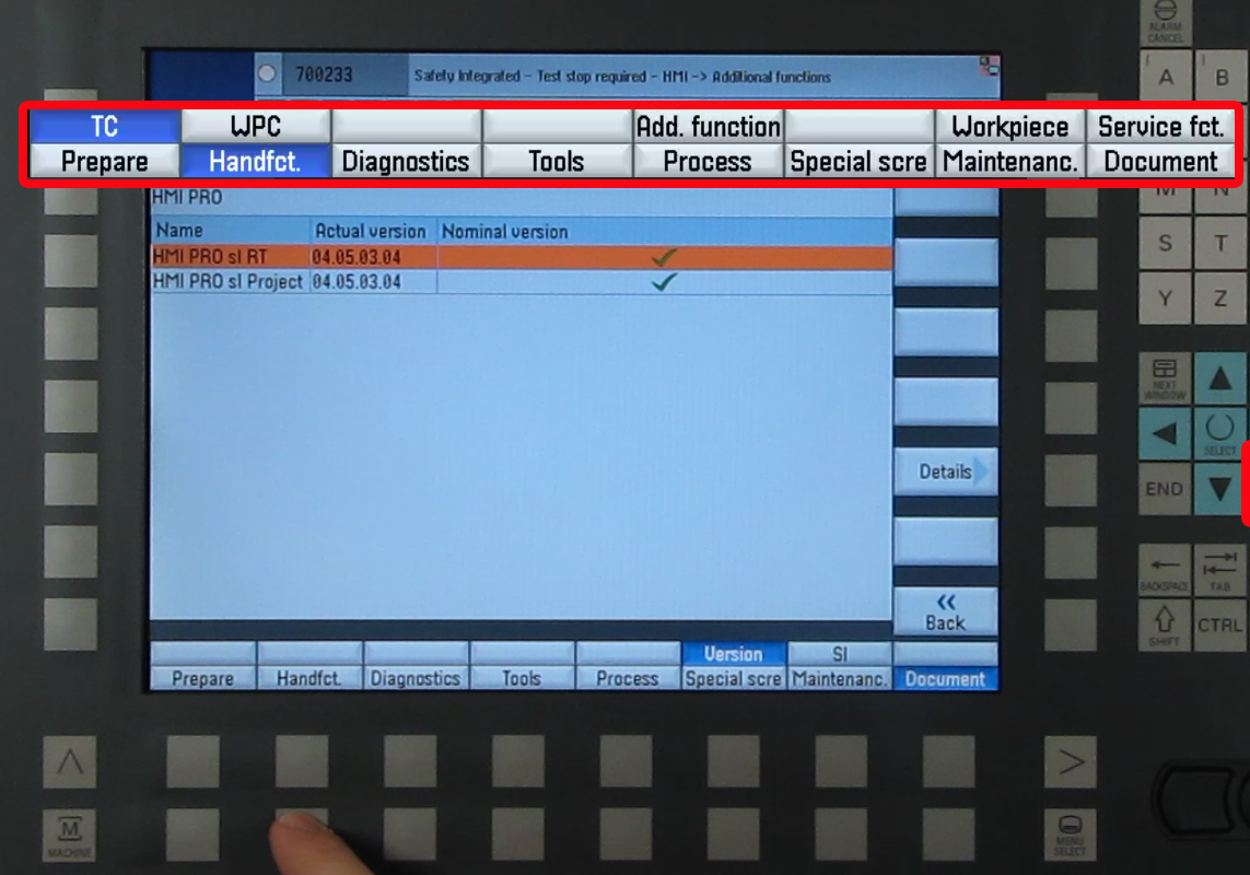
At the Prepare screen, press the "Hand funct" lower horizontal softkey at the HMI Panel. Step 4: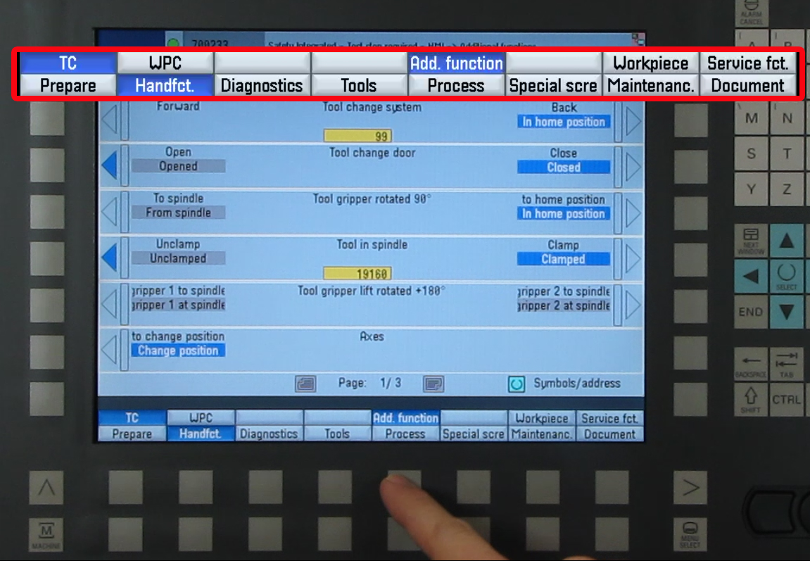
At the Hand Functions screen, press the Additional functions upper horizontal softkey. Press General Functions if the General Functions menu does not appear. Step 5: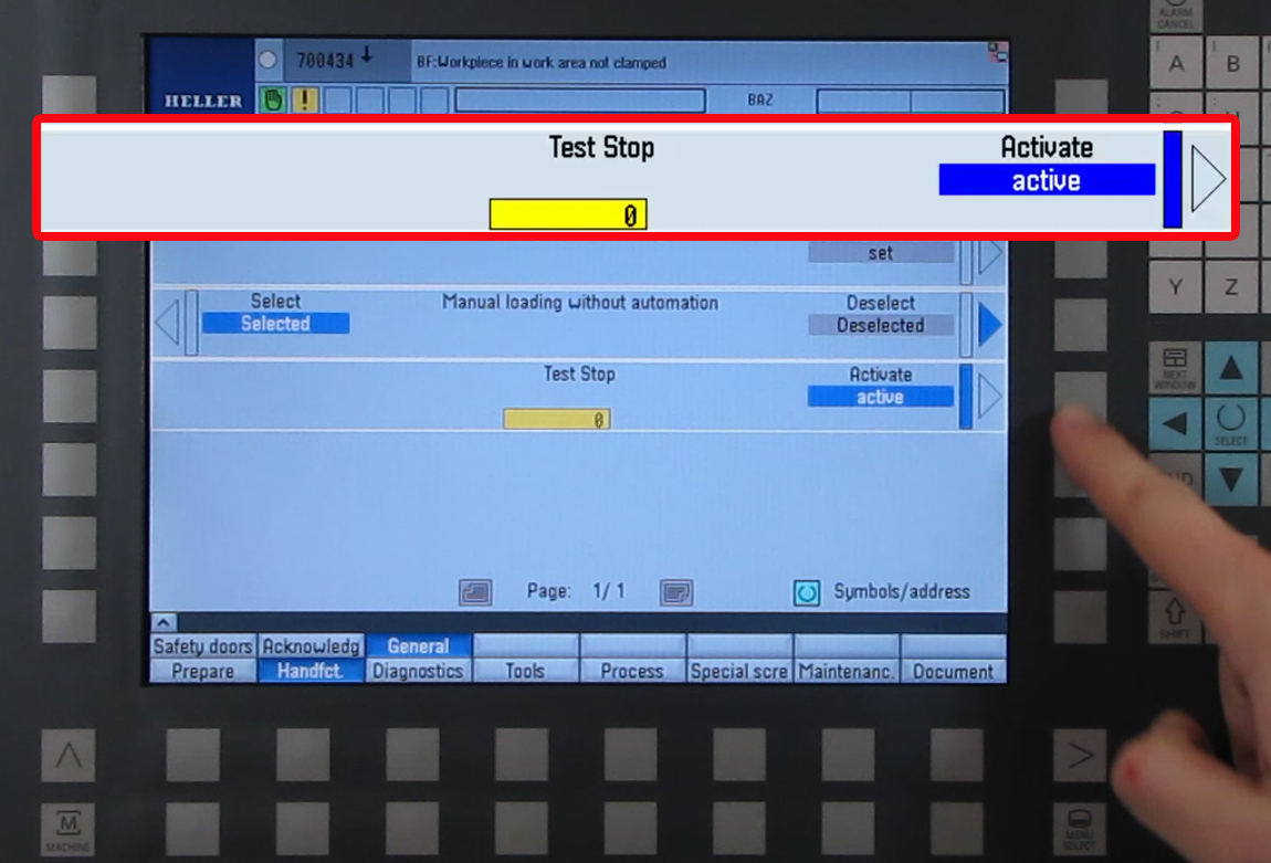
In the General Screen- press "Activate" softkey on the "Test Stop" function. The active field will turn blue. Step 6: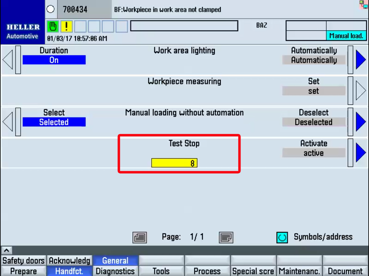
After the brake test is finished, a status message is output...
Step 7:
|