Functions in Auto Linked ModeSwitching to automatic loadingWorkpieces are inserted directly into the fixture machine via the
loading hatch (raw part) or removed from there (finished part). For
the loading and unloading processes, the Z-axis of the machine
travels to the loading position and the loading hatch is opened. The
coordination for the loading and unloading processes is
accomplished by the loader controller via the loader interface. 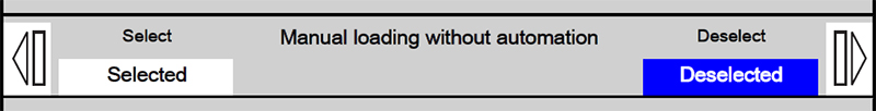
Opening the "General" HMI screenStep 1:Preconditions:
Press the Setup key. 
The machine is removed from the system linkage. Setup mode is activated. With Data menu key call up the basic menu on the main operator panel. Press the "HMI" softkey. Step 2:
Press lower horizontal softkey "Man.funct.". Step 3:Press upper horizontal softkey "General". Switching over to automatic modeStep 1:
Press the right-hand softkey for the "..." line.
Checking the loader interfaceThe HMI "Interface" screen can be called in order to gain detailed
insight into the automated loading and unloading of the machine via
the loader. Individual interface signals are displayed, which can also
be set manually if required.
Opening HMI "Interface" screenStep 1:
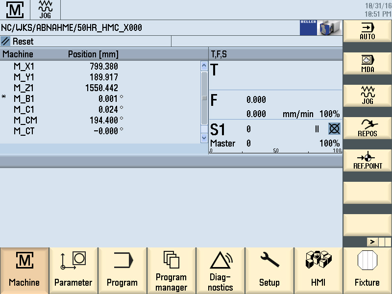
Preconditions:
With Data menu key call up the basic menu on the main operator
panel. Step 2:
Press lower horizontal softkey "Maintenance". Step 3:
Press upper horizontal softkey "Interface". Loading Interface PagesPage 1: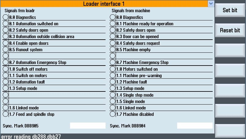
The HMI screen comprises several pages to accommodate the
numerous interface signals. Selecting the orange title line opens a
pull-down menu via which the other pages can be called up.
The interface bits can be controlled as follows:
Page 2: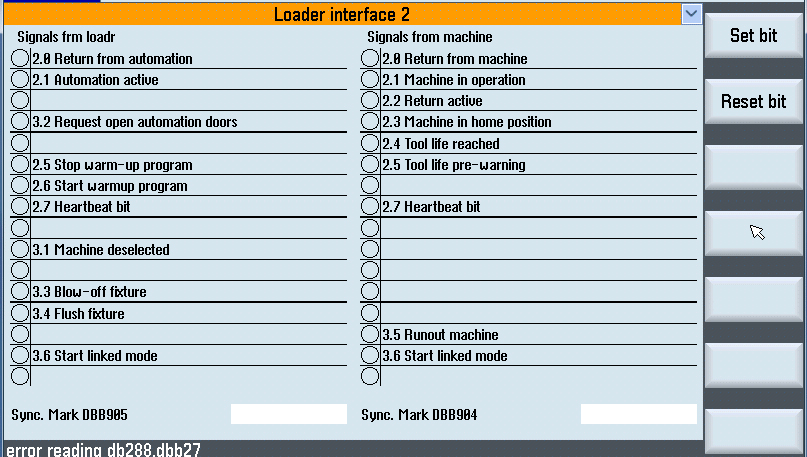
The HMI screen comprises several pages to accommodate the
numerous interface signals. Selecting the orange title line opens a
pull-down menu via which the other pages can be called up.
The interface bits can be controlled as follows:
Page 3: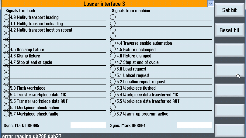
The HMI screen comprises several pages to accommodate the
numerous interface signals. Selecting the orange title line opens a
pull-down menu via which the other pages can be called up.
The interface bits can be controlled as follows:
Page 4: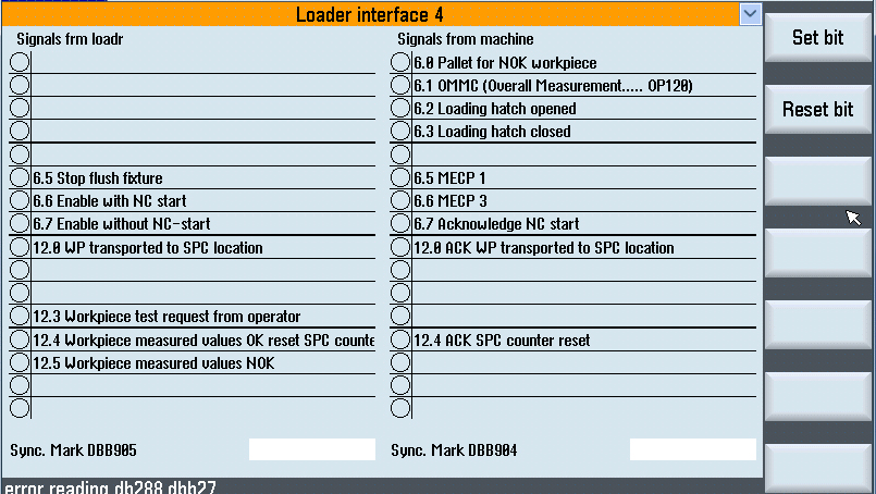
The HMI screen comprises several pages to accommodate the
numerous interface signals. Selecting the orange title line opens a
pull-down menu via which the other pages can be called up.
The interface bits can be controlled as follows:
Page 5: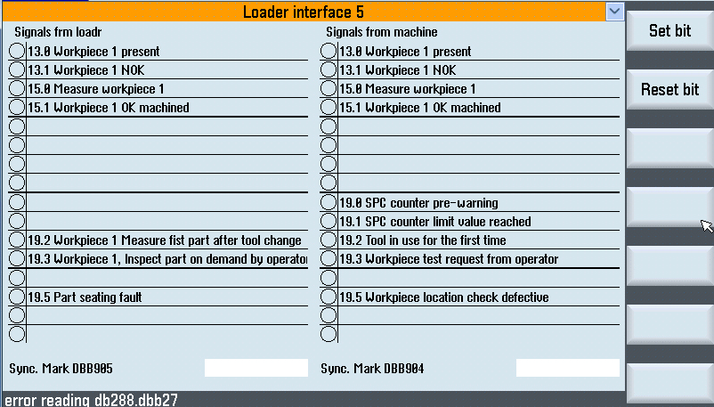
The HMI screen comprises several pages to accommodate the
numerous interface signals. Selecting the orange title line opens a
pull-down menu via which the other pages can be called up.
The interface bits can be controlled as follows:
home positionThe home position is the defined starting point for many NC programs. In the home position, the axes move to their start position. Machining of the workpiece can be started from here. Step 1: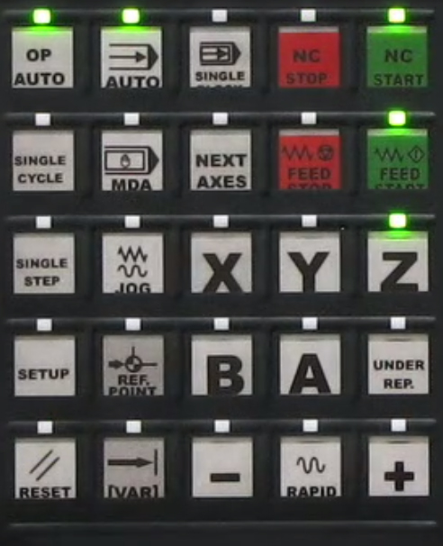
Preconditions:
Press the Auto and OP Auto Keys. Step 2:Press the Master Return key.
The lamp comes on when the home position is reached. Move machine to home positionStep 1:
The home position is the defined starting point for many NC
programs. In the home position, the Z-slide is retracted and in the "Start position". Machining of the workpiece can be started from here.
Press OP Auto and Auto keys. Step 2:Press the Master Return key.
The lamp comes on when the home position is reached. Starting productionStep 1:Preconditions:
Press the Interlinked Operation Mode (OP Auto) key.
Step 2:Press the Start/Step key.
The system operates cyclically in continuous operation. Runout MachineThe basic sequence for loading and unloading workpieces in automatic production mode can be defined via the "Runout" HMI function. Standard sequence: "Runout" deactivated
Special sequence: "Runout" activated:
Activating runoutStep 1:A new workpiece type is to be produced. An old workpiece type is
still located in the machine and is to be unloaded.
Press the left-hand softkey. Starting the unloading operationStep 1:Press the Interlinked Operation Mode (OP Auto) key. Step 2:Press the Start/Step key.
Deactivating runout againStep 1:Preconditions:
Press the left-hand softkey. If an irregularity was discovered or a tool fracture occurred during machining, the operator can systematically unload the workpiece. To do this, the workpiece status must be set manually to "NOK workpiece for unloading". This unqualified part (NOK part) is picked up by the loader and set down at a special location (e.g. SPC location). Declaring workpiece as NOK partStep 1: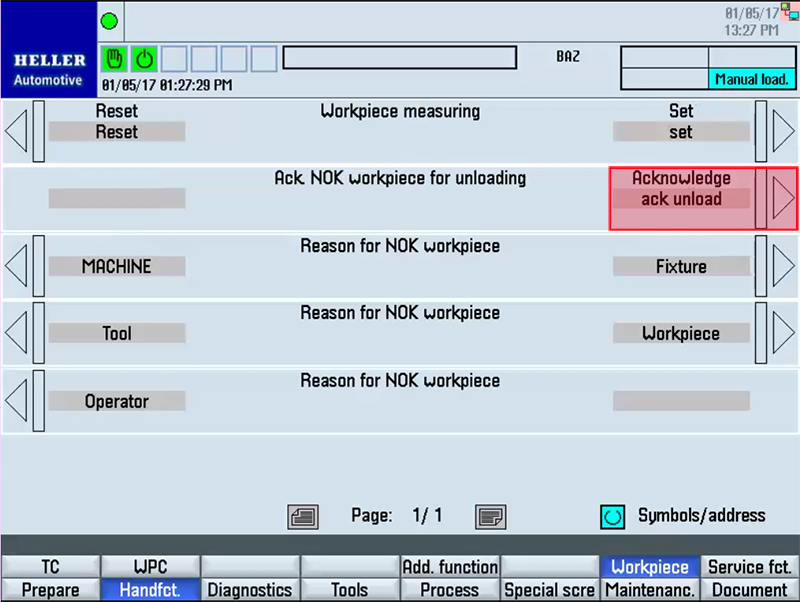
Preconditions:
Press the right-hand vertical softkey which is assigned to the "..."
line. Unloading NOK partStep 1:Preconditions:
Press the Interlinked Operation Mode (OP Auto) key. Step 2:Press the Start/Step key. If malfunctions occur, the machine stops in its current position for
safety reasons.
An error message is displayed on the screen. Calling up the "Acknowledgment" HMI screenStep 1:Preconditions:
Press the Setup key. Step 2:Press lower horizontal softkey "Man.funct.". Operation at the main operator panel or HT8If operation is toggled between the stationary operator panel (main
operator panel) and the mobile handheld operating unit (HT8), the
mobile handheld operating unit can remain inserted on the main
operator panel.
Operation at the HT8Step 1: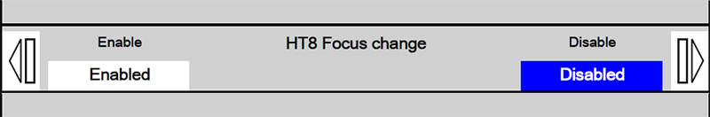
Press the right softkey "..." for the "HT8 Focus change" line. Operation is transferred from the stationary operator panel to the mobile handheld operating unit. Operation at the main control panelStep 1: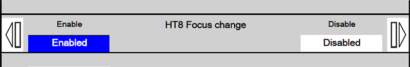
Press the left softkey "..." of the "HT8 Focus change" line. Operation is transferred from the handheld operating unit to the stationary operating unit. Reset machining depthThe control has a depth marker for re-entry into the last machining
step. Step 1: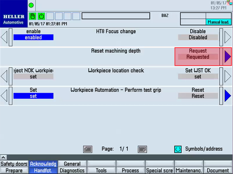
Preconditions:
Press the right softkey "Requested" for assigning to the "Reset machining depth" line. Step 2:Press the NC Reset key. Acknowledging workpiece location checkThe control has reported a workpiece location error.
Preconditions:
Confirming location check as OKStep 1: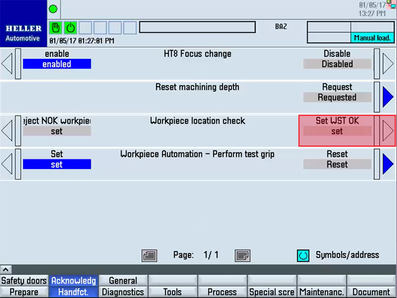
Preconditions:
Press the right softkey "Set WST OK" for assigning to the "..." line. Confirming location check as NOKStep 1: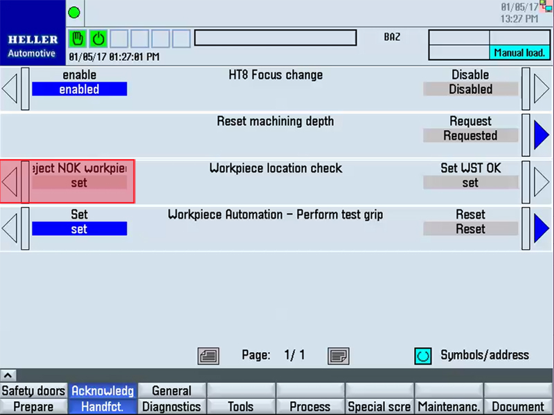
The location fault cannot be corrected. The error message is still
displayed. Acknowledge test grip of loaderWhenever the workpiece data register of the machine is faulty, the
control sends a request to the loader to execute a test grip. Step 1: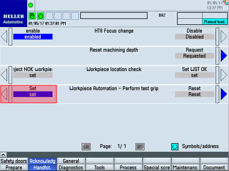
Preconditions:
Press the left softkey "Set" for assigning to the "..." line. |