Description: The document explains the procedure for replacing a faulty NCU or NX.
Particularities: Replacing the NCU or the CF card always necessitates a NCU reset. This is because a data comparison is run between the NCU and CF card and this requires series commissioning procedures to be imported when the NCU is replaced. Wherever possible,
new series commissioning procedures should be created beforehand.
Procedure for Replacing a NCU
Hardware replacement:
- Replace faulty NCU with a new module. It must be ensured that all cables are correctly inserted to prevent errors occurring in the topology.
- Remove the CF card from the fault NCU and insert into the new NCU.
Commissioning:
- Switch-on machine and wait for the NCU to power-up. If a "1" or a "2" appears in the 7-segment display, the NCU and PLC must be reset.
- Now reset PLC and NC.
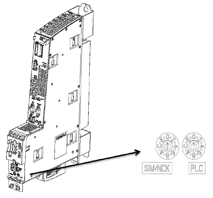
- Do this by setting the SIM/NCK rotary switch on the NC to 1 and on the PLC to 3
- Switch the machine off and then on again
- After power-up, turn the SIM/NCK to 0 (7-segment display at 5)
- Now use the PLC rotary switch to set the combination 2-3-2. The LED will start to flash (3s) and then light up permanently.
- Now turn the PLC switch to 0. The machine will power up!
- After power-up, set the manufacturer's password.
- Import series commissioning for NC, PLC.
- After importing the series commissioning procedures, switch the machine off and back on again.
Check the actual position:
- Depending on whether or not current series commissioning procedures were created prior to the replacement, the axis position may be incorrect after the backup is imported. The positions of all axes should be checked and corrected if necessary.
- The cartridge management system and pallet management system must then be checked.
- When importing old series commissioning procedures, all tools in the magazine/spindle must be unloaded and reloaded, as the assignment and the geometry of the tools are old.
Position of the Commissioning Switch on a NCU:
Procedure for Replacing a NX:
No data is lost when the NX assembly is replaced. The data for the NX are provisioned from the CF card in the NCU during power-up. Only topology and firmware are checked during an NX replacement!
Description: This document describes how to replace the fan or battery module.
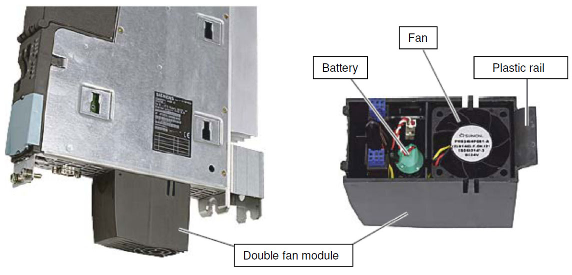
Tasks: The fan/battery module carries out the following tasks:
- CPU cooling
- SRAM buffering (if the SuperCap is insufficient)
The control unit monitors the temperature inside the sub-assembly and the fan function. The fan is activated if the temperature exceeds a specific threshold (40 degrees).
Fan faults are indicated and can be read out via the diagnosis buffer. However, the NCU switches off completely after 1 minute, thus interrupting the connection to the TCU. There diagnostic buffer cannot then be read-out.
| CAUTION: |
| The control unit cannot be operated without fans, i.e. the control unit will not power up without an operable fan/battery module! In this case, all LEDs illuminate orange, the RDY LED flashes orange/red and the value 8 appears in the 7-segment display. |
| NOTE: |
| The fan/battery module should be replaced when the control is switched on, otherwise data could be lost (S-RAM). Please stop the machine beforehand and switch off the motors. |
Replace the Module:
To replace the fan/battery module, proceed as follows:
(Points 3 and 4 are only relevant when replacing the battery.)
Step 1:
|
|
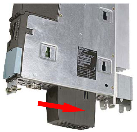
Press the fan/battery module backwards slightly.
This releases the module from its front catch. |
Step 2:
|
|
Hold the fan/battery module tilted forward and pull the plastic rail out of the control unit recess. |
Step 3:
|
|
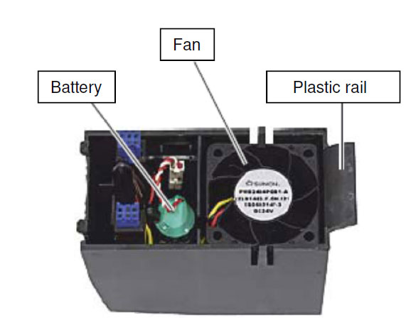
Remove the battery with a screwdriver (flat) and loosen the connection of the battery with the module by pulling off the plug. |
Step 4:
|
|
Connect the plug on the cable of the new battery to the counterplug in the fan/battery module and press the battery into place. |
Step 5:
|
|
Hold the fan/battery module tilted forward with the open side facing upward (battery visible). |
Step 6:
|
|
Push the plastic rail back into the recesses on the underside of the control unit. |
Step 7:
|
|
Tilt the fan/battery module upwards until the front catch clicks into place. |


