Replace Electrical Cabinet Axis Drives

Replace Solution Line Modules

These Solution Line modules do not contain memory chips. A data backup before replacement is therefore not required.

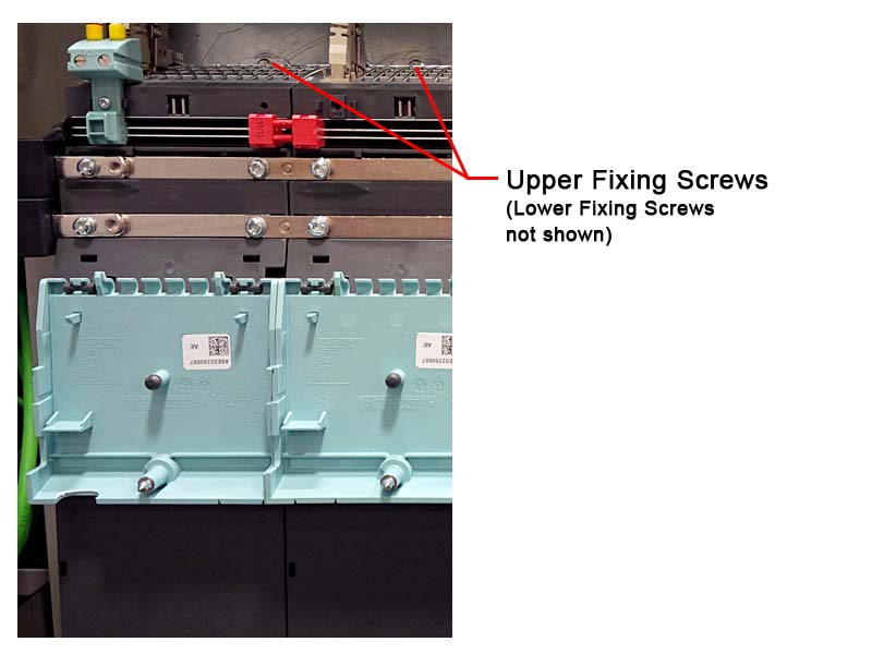
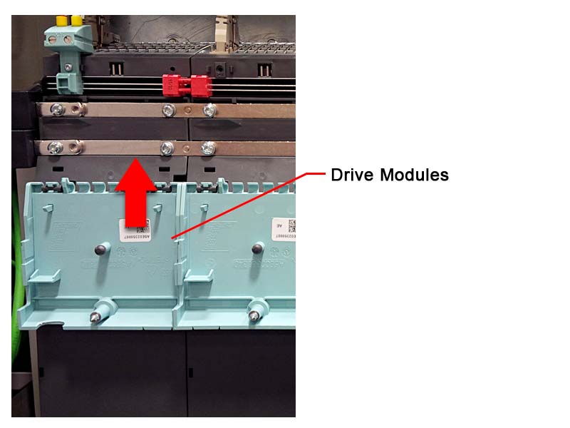
Description:

The Solution Line modules are bolted to the rear wall of the control cabinet.

Machine is switched off and secured to prevent restart.
DANGER:
Risk of injury from live components in the control cabinet and within the Solution Line modules. Particular risk posed by the intermediate circuit voltage of 600 V in drive train. Dangerous voltage remains for approx. 5 minutes after all voltages are switched off.

Do not open Solution Line modules until 5 minutes have lapsed.

Step 1

 
Do not open control cabinet until 5 minutes have lapsed.

Step 2

 
Loosen all cable connections on the Solution Line module concerned. These are described in the wiring diagram.

Step 3

 
Unlock the protective hood safety catch and fold down the protective hood. If necessary, repeat the procedure on the Solution Line modules located to the left and right.

Step 4

 
DANGER:

Electric shock from touching live parts.

Risk of injury from live components in the control cabinet.

Components must be properly checked for live and residual voltages before proceeding.

Release connections within the Solution line modules:
  • Unscrew and remove plug.
  • Evenly pull off connection element from both modules and store in a safe place.
  • Slightly loosen screws on both the upper and the lower busbar.
  • Fold up the moving connectors of the lower and upper busbars to the right.

Step 5

 
Slightly loosen upper and lower fixing screws on rear wall of control cabinet (do not remove).

Step 6

 
CAUTION:
Malfunction or damage to drive if module is incorrect. The new module must have the same mechanical and electrical features as the old one.

Compare nameplate on new and old module. The nameplates must be identical, including serial number.

Lift module slightly and remove from the control cabinet.

Step 7

 
Fit new module in the reverse order to removal.

Step 8

 
Attach a cable connections. These are described in the wiring digram.
  • Make sure that all cable connections are correctly attached. If not, topology faults will occur.

Step 9

 
Carefully tighten mains connections and earth connections.

Step 10

 
Close protective hoods, they must audibly engage.

Step 11

 
Close the control cabinet.

Step 12

 
Switch the machine on.